Commissioning • Connection examples
Chapter 3
Commissioning
Automation PC 810 with GM45 CPU board user's manual V1.28
199
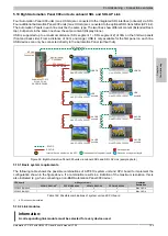
5.11.2 Link modules
Information:
A corresponding link module must be selected for every device used.
Model number
Description
Note
5DLSDL.1000-01
Automation Panel Link SDL transceiver
Connections for SDL in, transfer of display data, touch screen, USB 1.1, matrix keys, and service data,
24 VDC (screw clamp 0TB103.9 or cage clamp 0TB103.91 sold separately).
For Automation Panel 900
5AC801.SDL0-00
APC810 AP Link SDL transmitter
Automation Panel SDL link transmitter
For Automation PC 810
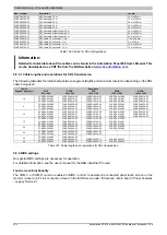
Table 167: Link modules
5.11.3 Cables
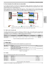
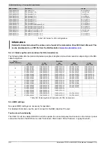
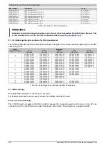
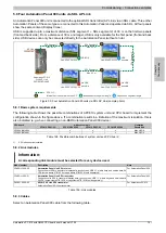
For a selection of SDL cables for connecting the AP900 display to the AP900 display, see see "Cables" on page 182.
For a selection of SDL cables for connecting the AP800 display to the AP900 display, see see "Cables" on page 184.
Information:
Detailed technical data about the cables can be found in chapter "Accessories".
5.11.3.1 Cable lengths and resolutions for SDL transmission
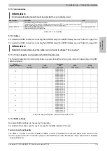
The following table lists the relationship between segment lengths and maximum resolution depending on the SDL
cable being used:
Resolution
Cables
Segment length [m]
VGA
640 x 480
SVGA
800 x 600
XGA
1024 x 768
SXGA
1280 x 1024
UXGA
1600 x 1200
1.8
-
-
-
-
-
-
-
-
5CASDL.0018-00
5CASDL.0018-01
5CASDL.0018-20
5CASDL.0018-03
-
-
-
-
-
-
-
-
5
-
-
-
-
-
-
-
-
5CASDL.0050-00
5CASDL.0050-01
5CASDL.0050-20
5CASDL.0050-03
-
-
-
-
-
-
-
-
10
-
-
-
-
-
-
-
-
5CASDL.0100-00
5CASDL.0100-01
5CASDL.0100-20
5CASDL.0100-03
-
-
-
-
-
-
-
-
15
-
-
-
-
-
-
-
-
5CASDL.0150-00
5CASDL.0150-01
5CASDL.0150-20
5CASDL.0150-03
-
-
-
-
-
-
-
-
20
-
-
-
-
-
-
5CASDL.0200-00
5CASDL.0200-20
5CASDL.0200-03
-
-
-
-
-
25
-
-
-
-
-
-
5CASDL.0250-00
5CASDL.0250-20
5CASDL.0250-03
-
-
-
-
-
-
30
-
-
-
-
-
-
5CASDL.0300-10
5CASDL.0300-13
5CASDL.0300-30
-
-
-
-
-
-
40
-
-
-
-
-
-
5CASDL.0400-10
5CASDL.0400-13
5CASDL.0400-30
-
-
-
-
-
-
Table 168: Segment lengths, resolutions and SDL cables
5.11.4 BIOS settings
No special BIOS settings are necessary for operation.
For detailed information, see the user's manual for the B&R industrial PC used.
Touch screen functionality
The COM C or COM D must be enabled in BIOS in order to operate the connected panel touch screen on the
monitor / panel or AP Link connection (found in the BIOS menu under "Advanced - Main board / Panel Features
- Legacy Devices").


