X20 system modules • Bus controllers System modules • X20PS9400
X20 system User's Manual 3.10
573
Product ID
X20PS9400
Bus controller / X2X Link supply output
Nominal output power
7.0 W
Parallel operation
Yes
2)
Redundant operation
Yes
Overload behavior
Short circuit / temporary overload protection
Input I/O supply
Input voltage
24 VDC -15% / +20%
Fuse
Required line fuse: Max. 10 A, slow-blow
Reverse polarity protection
No
Output I/O supply
Rated output voltage
24 VDC
Behavior if a short circuit occurs
Required line fuse
Permitted contact load
10.0 A
Interfaces
Service interface
Signal
RS232
Design
Connection made using 12-pin X20TB12 terminal block
Max. transfer rate
115.2 kbit/s
Operating conditions
Mounting orientation
Horizontal
Yes
Vertical
Yes
Installation at elevations above sea level
0 to 2000 m
No limitations
>2000 m
Reduction of ambient temperature by 0.5°C per 100 m
EN 60529 protection
IP20
Environmental conditions
Temperature
Operation
Horizontal installation
-25 to 60°C
Vertical installation
-25 to 50°C
Derating
See section "Derating"
Storage
-40 to 85°C
Transport
-40 to 85°C
Relative humidity
Operation
5 to 95%, non-condensing
Storage
5 to 95%, non-condensing
Transport
5 to 95%, non-condensing
Mechanical characteristics
Note
Order 1x X20TB12 terminal block separately
Order 1x X20BB8x bus base separately
Spacing
12.5
+0.2
mm
Table 178: X20PS9400 - Technical data
1)
The specified values are maximum values. The exact calculation is also available for download as a data sheet with the other module documentation on
the B&R website.
2)
In parallel operation, only 75% of the rated power can be assumed. It is important to make sure that all power supplies operating in parallel are switched
on and off at the same time.
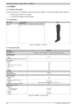
4.6.3.4 LED status indicators
Figure
LED
Color
Status
Description
Off
No power to module
Single flash
RESET mode
Blinking
PREOPERATIONAL mode
r
Green
On
RUN mode
Off
No power to module or everything OK
e
Red
Double flash
LED indicates one of the following states:
•
The bus controller / X2X Link supply for the power supply is overloaded
•
I/O supply too low
•
Input voltage for bus controller / X2X Link supply too low
e + r
Red on / Green single flash
Invalid firmware
Off
The bus controller / X2X Link supply is within the valid limits
l
Red
On
The bus controller / X2X Link supply for the power supply is overloaded
Off
No data traffic via service interface
S
Yellow
On
Data is being transmitted via the service interface
Table 179: LED status indicators
Summary of Contents for X20 System
Page 2: ......


