X20 system modules • Bus controllers • X20BC00G3
X20 system User's Manual 3.10
561
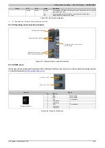
4.5.11.6 RJ45 ports
Information about cabling X20 modules with an Ethernet interface can be found in the module's download section
IN (IF1)
OUT (IF2)
IN
OUT
Pinout
Interface
Pin
Ethernet
1
TXD
Transmit data
2
TXD\
Transmit data\
3
RXD
Receive data
4
Termination
5
Termination
6
RXD\
Receive data\
7
Termination
1
Shielded RJ45 port
8
Termination
Table 166: Pinout for RJ45 port
4.5.11.7 EtherCAT network address switch
A slave alias address can be set using the two network address switches on the bus controller. During the initial-
ization phase (during start-up), the bus controller writes the value of the address switch to the ESC register 0x12
or 0x13. However, the value is only accepted in the register if the value of the switch value is between 0x00 and
0xFA (decimal 250).
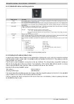
Switch position
Description
0x00 to 0xFA
Writes the address switch value to the "Station Alias" register.
0xFB to 0xFE
Address switch value not used. ESC Alias registers not changed.
0xFF
Address switch value not used. ESC Alias registers not changed. The bus controller boots with the default values
if the address switch is set to the value "0xFF" before a restart. All set parameters remain unchanged in flash
memory.
Table 167: Addresses
The master determines whether the alias address is used for the slave addressing by setting the corresponding
bit in the ESC DL control register (bit 24).
Summary of Contents for X20 System
Page 2: ......

