X20 system modules • Motor controllers • X20MM4456
1958
X20 system User's Manual 3.10
Product ID
X20MM4456
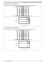
PWM pulse width
PWM mode
15-bit + sign ≥10 ns
Current mode
15-bit + sign ≥10 ns
Isolation voltage between channel and bus
500 V
eff
Operating conditions
Mounting orientation
Horizontal
Yes
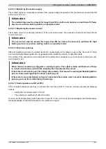
Installation at elevations above sea level
0 to 2000 m
No limitations
>2000 m
Reduction of ambient temperature by 0.5°C per 100 m
EN 60529 protection
IP20
Environmental conditions
Temperature
Operation
Horizontal installation
0 to 50°C
Vertical installation
Not permitted
Derating
-
Storage
-25 to 70°C
Transport
-25 to 70°C
Relative humidity
Operation
5 to 95%, non-condensing
Storage
5 to 95%, non-condensing
Transport
5 to 95%, non-condensing
Mechanical characteristics
Note
Order 2x X20TB12 terminal block separately
Order 1x 0TB3103-7020 terminal block separately
Spacing
87.5
+0.2
mm
Table 704: X20MM4456 - Technical data
4.25.5.4 LED status indicators
For a description of the various operating modes, see the 2.11.1 "re LEDs" section.
Status LED, left
Figure
LED
Color
Status
Description
Off
No power to module
Single flash
RESET mode
Double flash
BOOT mode (during firmware update)
1)
Blinking
PREOPERATIONAL mode
r
Green
On
RUN mode
Off
No power to module or everything OK
e
Red
On
Error or reset status
e + r
Red on / Green single flash
Invalid firmware
1 - 8
Green
Input state of the corresponding digital input
M1 + M2
Orange
On
The corresponding output is active
1)
Depending on the configuration, a firmware update can take up to several minutes.
Status LED, right
Figure
LED
Color
Status
Description
9 - 16
Green
Input state of the corresponding digital input
M3 + M4
Orange
On
The corresponding output is active
Summary of Contents for X20 System
Page 2: ......


