


X20 system modules • Motor controllers • X20MM4331
1948
X20 system User's Manual 3.10
4.25.4.9 Protection
The power supply line should be protected by a circuit breaker or a fuse. In general, dimensioning the supply line
and overcurrent protection depends on the structure of the power supply (modules can be connected individually
or in groups).
Information:
The effective current for the power supply depends on the load, but is always less than the sum of the
output currents. Make sure that the maximum nominal current of 31 A per pin is not exceeded on the
power supply terminals of the power unit.
When choosing a suitable fuse, the user must also account for characteristics such as aging effects, temperature
derating, overcurrent capacity and the definition of the rated current, which can vary by manufacturer and type. In
addition, the fuse that is selected must also be able to handle application-specific characteristics (e.g. overcurrent
that occurs in acceleration cycles).
The cross section of the power mains and the rated current of the overcurrent protection used are chosen according
to the current load so that the maximum current load for the cable cross section selected (based on the type of
layout, see table) is greater than or equal to the current load in the power mains. The rated current of the overcurrent
protection must be less than or equal to the maximum current load for the cable cross section selected (based
on the type of layout, see table):
I
Mains
≤
I
b
≤
I
Z
Mains
≤
Fuse
≤
Line/cable
Current load of the cable cross section I
Z
/ rated current of the over current protection I
b
[A] according to type
of installation in an ambient air temperature of 40°C in accordance to IEC 60204-1
Wire cross section [mm²]
B1
B2
C
E
1.5
13.5 / 13
13.1 / 10
15.2 / 13
16.1 / 16
2.5
18.3 / 16
16.5 / 16
21 / 20
22 / 20
4.0
24.0 / 24.0
23.0 / 20.0
28.0 / 25.0
30.0 / 25.0
6.0
32.0 / 32.0
29.0 / 25.0
36.0 / 32.0
37.0 / 32.0
Table 701: Cable cross section of the mains supply line depending on the type of layout
The tripping current of the fuse cannot exceed the rated current of fuse I
b
.
Type of layout
Description
B1
Wires in conduit or cable duct
B2
Cables in conduit or cable duct
C
Cables or wires on walls
E
Cables or wires on open cable tray
Table 702: Type of layout for the mains supply line
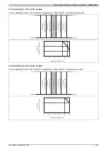
4.25.4.10 Derating
In order to be able to operate the motor module over the entire temperature range, only modules with a maximum
power loss of of 0.5 W can be installed next to the motor module or respective turn-off times must be implemented.
If the neighboring modules have a higher power loss and all channels are operated continuously, the motor current
must be derated.
When a motor is switched on, the current is increased for a short time. This behavior has no influence on the
derating.
Summary of Contents for X20 System
Page 2: ......


