


X20 system modules • Digital output modules • X20DO4623
X20 system User's Manual 3.10
1173
4.15.14.9.3 Digital outputs
The output status is transferred to the control switch asynchronously to the connected network. The outputs switch
on when the voltage crosses zero and switch off when the current crosses zero.
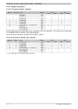
4.15.14.9.3.1 Switching state of digital outputs 1 to 4
Name:
DigitalOutput
DigitalOutput01 to DigitalOutput04
The switching state of digital outputs 1 to 4 are stored in this register.
Function model 0 - Standard only:
The "packed outputs" setting in the AS I/O configuration is used to determine whether all of this registers' bits
should be set up individually as data points in the AS I/O mapping ("DigitalOutput01" through "DigitalOutput0x") or
whether this register should be displayed as an individual USINT data point ("DigitalOutput").
Data type
Value
Information
0 to 15
Packed outputs = on
USINT
See bit structure
Packed outputs = off or function model <> 0 - Standard
Bit structure:
Bit
Name
Value
Information
0
Digital output 01 reset
0
DigitalOutput01
1
Digital output 01 set
...
...
0
Digital output 04 reset
3
DigitalOutput04
1
Digital output 04 set
Information:
The states are only applied when the channels are set to DIGITAL in Setting the output configuration.
When using the setting "packed outputs" ALL channels must be set to DIGITAL. Mixed operation is
not possible.
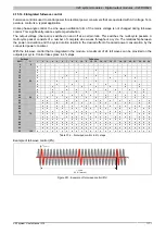
4.15.14.9.4 Analog outputs
The output value is transferred to the control circuit in sync with the connected power mains according to the
firing pattern table (see "Integrated full-wave control"). The analog value is output with a resolution of ~4% over a
duration of 24 complete waves. Values > 96% result in full control. Changes to the output value within an interval
are applied after the next zero crossover.
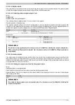
4.15.14.9.4.1 Setting the output value from the firing pattern table
Name:
AnalogOutput01 to AnalogOutput04
These registers are used to set the output value from the firing pattern table.
Values between 0 and 100 correspond to the output value for the respective channel in percent. Values above
100 correspond to 100%.
Data type
Value
USINT
0 to 100
Information:
The states in these registers are only applied when the channels are set to ANALOG in Setting the
Summary of Contents for X20 System
Page 2: ......


