X20 system modules • Digital output modules • X20DO4613
1158
X20 system User's Manual 3.10
4.15.13.8 Operating principle
The digital output module DO4613 was designed to control external triacs and thyristors.
The module is equipped with internal zero-crossing detection. Zero-crossing detection is the basis for a software
PLL that generates 200 times the zero-crossing frequency. The output signal of the PLL is the base timer for the
4 PWM outputs in both digital and analog mode.
Upon detection of lost periods or periods that are too short, control to the outputs is cut until the PLL is tuned
correctly. The tuning procedure can take several seconds. In addition, the "ZeroCrossingStatus" bit is set and the
error LED enabled (valid frequency range for the supply is 47 to 63 Hz).
Information:
The jitter of the output signals generated by the PLL and communication can reach 0.5%.
4.15.13.9 Operation with inductive loads
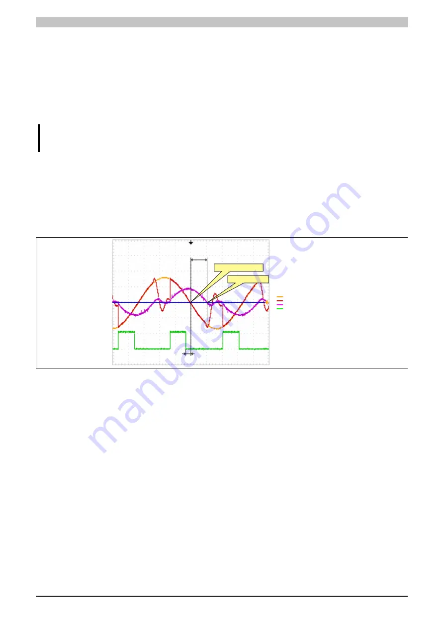
As inherent to its functional principal, the triac output is cleared when the current crosses zero. Because zero
crossing for current is delayed with inductive loads, it is possible that the triac will be fired again even though it is
not completely cleared at higher output values (between 50 and 100% depending on the inductance of the load).
In this case, a full-wave is output. This causes the available control range to be reduced (0 to 100%).
For control beyond the point of full-wave control (up to 100%), the value that is physically output no longer changes.
However, this does not cause damage to the module.
Switch-off delay caused by
Inductive load
CfO_SwitchOffValue in %
Zero crossing: Voltage
Zero crossing: Current
Input voltage
Output voltage
Output current
Internal firing signal for the triac
Summary of Contents for X20 System
Page 2: ......


