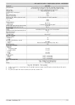
X20 system modules • Digital output modules • X20DO4322
1122
X20 system User's Manual 3.10
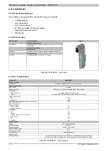
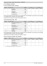
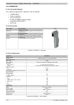
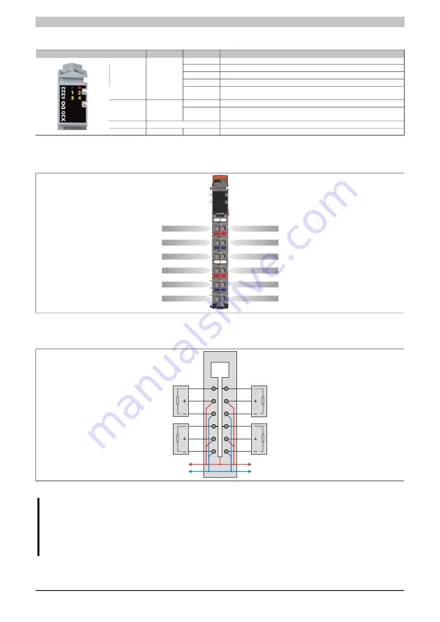
4.15.9.4 Status LEDs
Figure
LED
Color
Status
Description
Off
Module supply not connected
Single flash
Reset mode
Blinking
PREOPERATIONAL mode
On
RUN mode
r
Green
Flickering (ap-
prox. 10 Hz)
Module is in OSP state
Off
Module supply not connected or everything OK
e
Red
Single flash
Warning/Error on an I/O channel. Level monitoring for digital outputs has been
triggered.
e + r
Red on / Green single flash
Invalid firmware
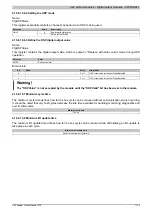
1 - 4
Orange
Output status of the corresponding digital output
Table 357: Status LEDs
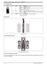
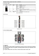
4.15.9.5 Pinout
1
X
20
D
O
4
32
2
2
DO 1
+24 VDC
GND
DO 2
+24 VDC
GND
GND
GND
DO 3
+24 VDC
DO 4
+24 VDC
3 4
3 4
r
e
Figure 334: Pinout
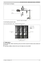
4.15.9.6 Connection example
GND
+24 VDC
GND
+24 VDC
DO
Ac
tu
at
or
1
Ac
tu
at
or
2
Ac
tu
at
or
4
Ac
tu
at
or
3
Figure 335: Connection example
Caution!
If the module is operated outside of specifications, the output current can increase above the maximum
permissible nominal current. This applies to individual channels and also to the summation current
for the module.
Therefore sufficient cable cross sections or external safety measures must be used.
Summary of Contents for X20 System
Page 2: ......


