black plug
torsion shaft
couple
bolt 3/8”
washer 3/8”
cable drum marked
with red paint
red plug
cable drum marked
with black paint
bolt 3/8”
washer 3/8”
roller bearing
slid
e
slid
e
roller bearing
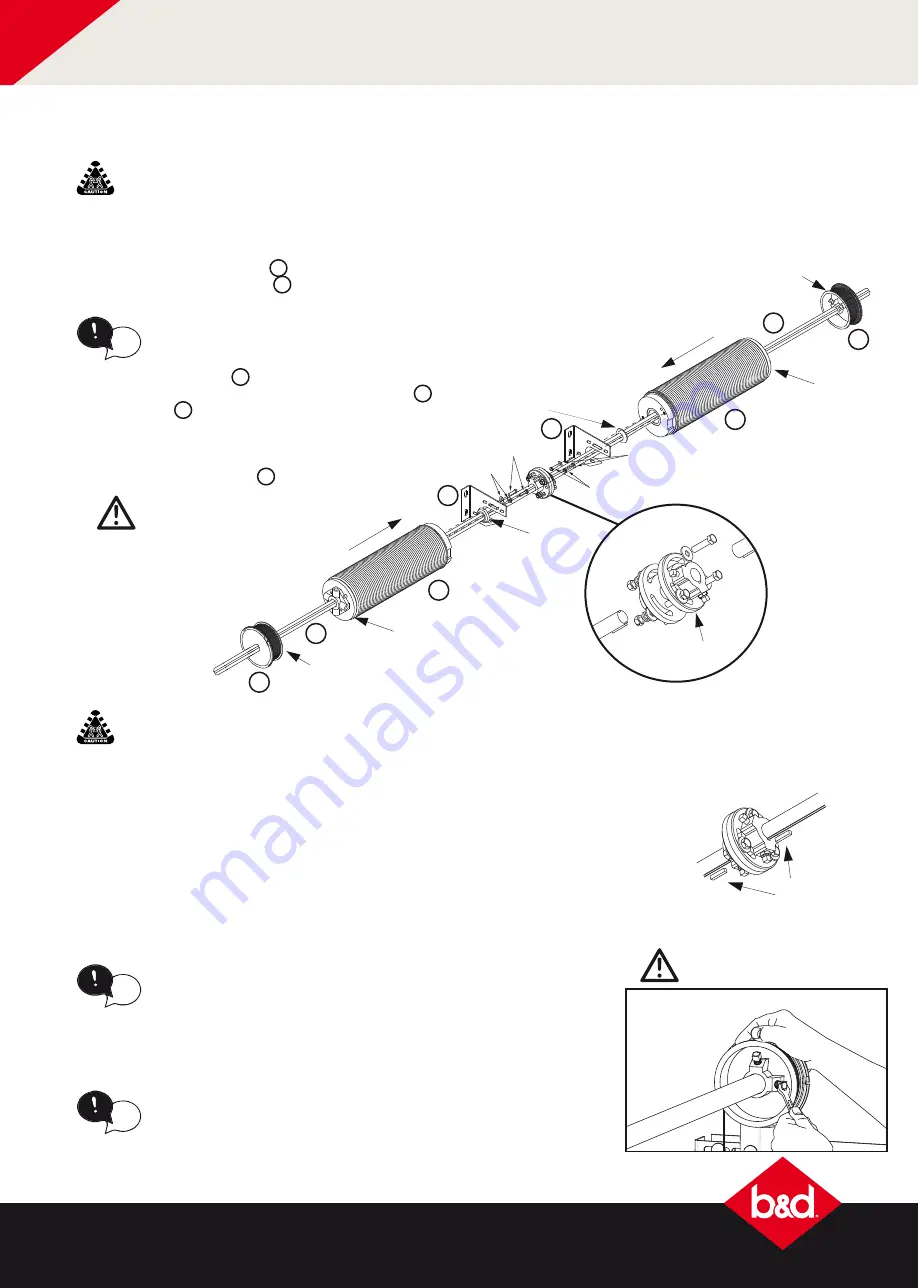
5.2 two piece shafts for large doors
The springs and drums for the counterbalance system are now colour coded to easily identify which
side of the centre bracket the spring is placed. Fig. 5.2.1.
a) Place the 2 x torsion bars
B
on the floor and slide the 2 x
HD spring anchor bracket
K
and roller bearings onto the
torsion bar, positioning them towards the middle.
b) Slide on the springs
I
, ensuring the roller bearing
is butted up against the spring anchor bracket
K
and spring
I
.
c) Connect each assembly together using 2 x 3/8”
washers and bolts.
d) Place the cable drums
J
on each end.
e) Mount the remaining 2 x spring
anchor brackets to the wall
above the horizontal track.
CAUTION:
DO NOT tighten
bolts in cable drums yet
TWO PERSON LIFT:
For large doors, this process may require two persons to lift into place and
a ladder or scissor lift to support while fixing into place.
TWO PERSON LIFT:
Next step may require two persons to lift into
place and a ladder or scissor lift to support while fixing into place.
insert key then fix into
place with grub screw
torsion
shaft key
torsion
shaft key
torsion
shaft key
Fig: 5.2.1
Fig: 5.2.2
a) Attach the lifting cable to the cable drum by slipping the cable into the slot
on the outside groove. (the ferrule will prevent the cable from coming out) .
b) Wind the cable by hand by turning the cable drum away from the door.
tip
Unwind the lifting cable from the
bottom panel.
CAUTION:
Be careful not to
over tighten the set-screws
Fig: 5.2.3
K
J
B
J
I
tip
The smaller end of the roller
bearing is to face the spring.
f) Lift and thread the right hand side of the assembly through the mounted spring
anchor bracket and fix the loose spring anchor bracket securely to the wall.
g) Assemble the torsion shaft couple, without tightening the bolts and slide onto
the end of the torsion bar, ready to connect to the other torsion bar.
h) Repeat step f) for the left hand side assembly.
i) Position the torsion shaft couple in the middle as shown in Fig 5.2.1, the axles
should be flush with each couple allowing free rotation to occur.
j) Cut torsion shaft key in half and insert into torsion bar at the torsion shaft
couple, and fix into place by tightening the grub screws on the shaft couple
Fig 5.2.2.
K
I
B
c) Once the cable is taut, slide the cable drum against the side bearing bracket
and tighten the screws to the torsion bar. Fig 5.2.3.
d) Proceed to section 3.8 to tension the springs.
tip
There must be no more than ONE turn of cable around the cable
drum. Too much cable will affect the spring tension.
20
The Designer Series
&
P7 Industrial
™
installation instructions


