


3.3
Electrical Installation
Refer to Table 3.2 on page 16 for full details on the electrical requirement for your specific model
prior to installation.
Electrical connections should be made by a qualified electrician in accordance with all applicable
codes or requirements. Use a separate branch circuit to power each machine. Do not share circuits
with lighting or any other equipment.
Because this is a vibrating machine, use SO cable (or similar) with a twist-lock plug to connect
the machine to main power. A shielded liquid tight or approved flexible conduit with proper
conductor of correct size installed in accordance with National Electric Code (USA) or other appli-
cable codes is required. The connection must be made by a qualified electrician using the wiring
diagram provided with the machine.
For personal safety and for proper operation the machine must be grounded in accordance with
state and local codes and in the USA in accordance with the National Electric Code, article 250-96.
The ground connection must be to a proven earth ground, not to conduit or water pipes.
Do not connect the ground to the neutral (N) leg at the terminal strip (if so equipped).
If a DELTA supply system is used, the high leg should be connected to L3, since control voltage is
derived from L1 and L2.
Note:
Ensure that all power connections are tight. Loose connections will
cause burned wires and contactors on electrically heated machines.
Check the electrical connections at the incoming power terminal block,
contactors, and heating elements at installation, after the first week of
operation, and quarterly thereafter. Failure of switchgear due to negli-
gence in this area is not covered under any warranty!
3.4
Gas Connection
3.4.1
Gas Supply Line
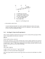
•
1” IPS pipe is recommended.
•
1” approved tubing is acceptable for lengths under 25 ft (6.1 m) if local codes and gas supplier
permit.
•
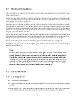
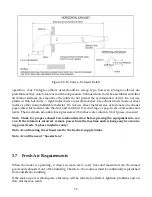
Must include 1/8” NPT minimum plugged tapping accessible for test gauge connection,
immediately upstream of the gas connection to the ironer (see figure 3.1 on page 9).
8


