background image

32

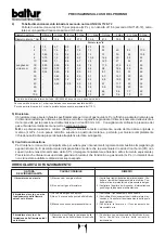
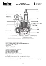
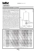
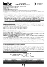
DUNGS VALVE

MODEL MB-ZRDLE...B01 AND B02

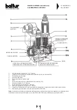
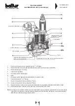
The monobloc DUNGS Model MB-ZRDLE is made up of:
a) Minimum gas pressure switch (3) and maximum gas pressure (12)
b) Gas filter (6)
c) Pressure regulator (stabilizer) (2) (only for version B01)
d) Safety valve (incorporated in the pressure regulator) which opens and closes rapidly (4)
e) Principle valve with two positions (1st flame and 2nd flame) which opens slowly with an adjustable initial rapid

release and rapid closing (8).

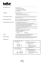
Before proceeding with regulation, read the following:
1) It is possible to reach the gas filter (6) in order to clean it, by removing one of the two side closing plates.
2) The pressure stabilizer can be regulated from 40 to 200 mm.W.C. by manoeuvring its regulating screw. It can be

reached by sliding the cover (2) to one side. The and viceversa is about 60 turns. Do not force against the end-of-
the-run position. Before starting up the burner, give the screw at least 15 turns towards the + sign. Around the
screw are arrows with symbols which indicate the sense of rotation to increase the pressure (in a clockwise
direction) and the sense of rotation to decrease pressure (in an anti-clockwise direction).

The stabilizer hermetically closes from “upstream” to “downstream” when there is no gas flow. Different  springs to

obtain different pressure values form those described above are not foreseen.

To regulate the pressure stabilizer, connect a water manometer to the rubber tube holder installed on the valve, to

tap Pa (7), in correspondence with the stabilizer exit.

3) It is not necessary to regulate the rapid opening and closing safety valve (4).
4) Principle valve (8).
Regulating the initial rapid release effects the 1st and 2nd opening positions of the valve.
Regulation of the rapid release and of the hydraulic brake modify the 1st and 2nd positions of the valve in proportion
to the output regulated. To carry out regulation, unscrew the protection cover (11) and use the back part of it as a tool
to turn the pin.
Rotation in a clockwise direction

= minor rapid release

Rotation in an anti-clockwise direction = greater rapid release

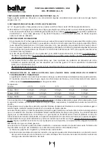
REGULATING THE FIRST POSITION (1ST FLAME)

Loosen the screw with the protruding cylindrical head (1)
Give the knob (10), which regulates the output for the 2nd flame, at least one turn in the direction of the arrow which
indicates the + sign (anti-clockwise direction).
ATTENTION: If this knob which regulates the 2nd flame is not given at least one turn towards the + sign, the valve will

not open in the 1st position.

Rotate the regulating ring (9) of the 1st flame in the direction indicated by the arrow towards the + sign (anti-clockwise
direction). As an indication, this should be a little more than two turns from the end-of-the-run position.
Then, when the 1st flame only is alight, rotate adequately ring (9) in order to obtain the gas delivery desired.
The complete run of the output regulator, from the - position to the + position, and viceversa, is about three and a half
turns. Rotation of the regulator in a clockwise direction, determines a reduction in delivery; rotation in an anticlockwise
direction increase delivery.

REGULATING THE SECOND POSITION (2ST FLAME)

Loosen the screw with the protruding cylindrical head (1)
Rotate the knob (10) in the direction indicated by the arrow for the + sign (anti-clockwise direction) as considered
necessary in order to obtain the gas delivery required for the 2nd flame.
The complete run of the regulator from the - position to the + position, and viceversa, is about FIVE turns. Rotate in a
clockwise direction to determine a reduction in delivery and in an anti-clockwise direction to increase it.
After regulating the gas delivery for the 1st and 2nd flame,remember to tighten home the screw (1) to avoid the
regulatormoving out of the position at which it has been set.

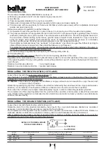
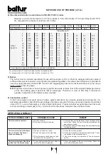
N° 0002910310

Rev. 26/09/97

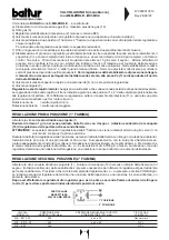
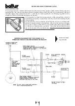
1st POSITION

2nd POSITION

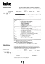
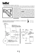
DETAILS OF TERMINAL BOARD

FOR VALVE MB-ZRDLE...

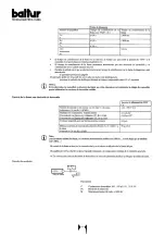
VALVE

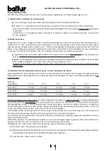
INLET MAX PRESSURE

ADJUSTTABLE OUTLET PRESSURE

TYPE OF GAS

MODEL

 (PE) mbar

FROM THE STABILIZER (PA) mbar

MB ...B01 S 20

200

from 4 to 20

Gas maturale

MB ... B01 S 50

360

from 4 to 50

L.P.G

MB ... B02

360

L.P.G.

Summary of Contents for SPARKGAS 3,6

Page 1: ...t is possible to cause dangerous accidents Lea atentamente las instrucciones antes de poner en funcionamento los quemadores y efectuar las tareas de mantenimiento Los trabajos que se efect en al quema...

Page 2: ...uemadores mixtos gas gas leo o gas fuel cuando los mismos se piden no conformes a la Norma CE o a la norma italiana UNI porque est n destinados a un uso especial no previsto en las normas arriba menci...

Page 3: ...agine Gialle alla voce Bruciatori sono a disposizione per 1 la Messa in funzione e la vidimazione del certificatodi garanzia la garanzia valida esclusivamente se detta messa in funzione viene effettua...

Page 4: ...ation Air regulation on the combustion head Maintenance Use of the burner 24 Gas burner controls 27 Combined DUNGS gas valve monobloc MB ZRDLE B01 B02 31 Notes on use of propane L P G Operation proble...

Page 5: ...vec vaporisateur 75 Principe de r glage d air Place des lectrodes 76 Servomoteur de commande volet d air 78 Schema electrique 79 INHALTSVERZEICHNIS SEITE Ausstattung 8 Anbringung des brenners am heizk...

Page 6: ...ricolose come la formazione di miscele tossiche ed esplosive Per chiarire meglio la situazione facciamo un esempio Per bruciare correttamente una quantit di combustibile corrispondente alla modesta po...

Page 7: ...rtenze particolari per l uso del gas Far verificare da personale professionalmente qualificato a che la linea di adduzione e la rampa siano conformi alle norme e prescrizioni vigentiDPR del 12 4 96 G...

Page 8: ...la gas 1 R fer nce de position de disque t te 2 Poign e de r glance de l air manuel 2 1 Servomoteur de r gulation air seulement dans la v rsion P 3 Connecteur 7 pol 3 1 Connecteur 4 pol seulement dans...

Page 9: ...EXAGONAL NUTS SECHSKANTMUTTERN TURCAS ECROUS PRIGIONIERI STUD BOLTS STEHBOLZEN PERNO CON TOPE GOUJONS GUARNIZIONE ISOLANTE ISOLATING GASKET DICHTUNG JUNTA JOINT ISOLANT MATERIALE A CORREDO STANDARD A...

Page 10: ...o per consentire un agevole smontaggio del bruciatore e o l apertura del portellone della caldaia La valvola gas DUNGS mod MB incorpora filtro e stabilizzatore della pressione gas pertanto sulla tubaz...

Page 11: ...quindi chiudere il rubinetto Attendere il tempo che si presume sufficiente in funzione delle condizioni specifiche affinch il gas presente nel locale si sia disperso all esterno e quindi ripristinare...

Page 12: ...aria nel bruciatore realizzi effettivamente questa condizione in caso contrario l apparecchiatura di comando e controllo non viene inserita il bruciatore resta fermo Precisiamo che se non si chiude i...

Page 13: ...automatico quindi non occorrono manovre di regolazione durante il suo funzionamento La posizione di blocco una posizione di sicurezza in cui il bruciatore si dispone automaticamente quando qualche co...

Page 14: ...14...

Page 15: ...15...

Page 16: ...16...

Page 17: ...17...

Page 18: ...regolazione erogazione 2 fiamma 11 Coperchio di protezione con uso manopola del dispositivo di regolazione dello scatto rapido iniziale 12 Pressostato gas massima solo per versione B02 e B01 S50 Nota...

Page 19: ...ne 11 e usare la sua parte posteriore come attrezzo per far ruotare il perno Rotazione oraria scatto rapido minore Rotazione antioraria scatto rapido maggiore REGOLAZIONE PRIMA POSIZIONE 1 FIAMMA Alle...

Page 20: ...e solo per impianti di piccola potenza La capacit di erogazione in fase di gas in funzione delle dimensioni del serbatoio e della temperatura minima esterna esposta solo a titolo indicativo nella segu...

Page 21: ...e che impurit di carattere accidentale arrivino al riduttore compromettendone il corretto funzionamento Precisiamo che i tradizionali filtri gas hanno un elemento filtrante in materiale non sufficient...

Page 22: ...2 Gas 2 Gas 3 Gas Diametro interno mm 13 2 16 6 22 2 27 9 36 6 41 5 53 8 69 6 81 8 2 1 5 2 7 6 0 11 23 35 4 1 0 1 8 4 1 7 4 15 24 45 82 135 6 0 80 1 5 3 2 6 1 12 19 35 66 108 8 0 70 1 3 2 8 5 2 10 6...

Page 23: ...pipeline in proximity to the burner to allow for easy di sassembly of the burner and opening of the boiler door The DUNGS mod MB valve incorporates a filter and a gas pressure stabilizer and therefor...

Page 24: ...ut one third the air passage between the head and the flame disk diffuser see Regulation of the combustion Head 3 Operate the regulators incorporated in the gas valves in such a way as to obtain the g...

Page 25: ...only increase the regulating value until it reaches intervention point and the burner should go to shut down To ublock the burner press the special pushbutton and return the pressure switch regulator...

Page 26: ...non necessary to carry out any kind at adjustment during its operating The block position is a safety position reached by the burner automatically when some of the components of the burners or the pl...

Page 27: ...27...

Page 28: ...28...

Page 29: ...29...

Page 30: ...30...

Page 31: ...re switch minimum 4 Safety valve 5 Pressure tap at gas entry 6 Filter 7 Pressure tap after pressure stabilizer Pa 8 Principle valve 1st and 2nd flame 9 Regulating ring 1st flame delivery 10 Regulating...

Page 32: ...as a tool to turn the pin Rotation in a clockwise direction minor rapid release Rotation in an anti clockwise direction greater rapid release REGULATING THE FIRST POSITION 1ST FLAME Loosen the screw w...

Page 33: ...d gas plant to ensure correct operation and safety Natural gasification from cylinder unit or tank can only be used for low power plant Supply capacity at gaseous stage depending on tank dimensions an...

Page 34: ...d that any impurities unexpectedly reach the reducer thus endangering the correct working It is impostant to point out that the usual filters do not have a cartridge filter element enough resistent to...

Page 35: ...3 8 Gas Gas 3 4 Gas 1 Gas 1 1 4 Gas 1 Gas 2 Gas 2 Gas 3 Gas Inner diameter mm 13 2 16 6 22 2 27 9 36 6 41 5 53 8 69 6 81 8 2 1 5 2 7 6 0 11 23 35 4 1 0 1 8 4 1 7 4 15 24 45 82 135 6 0 80 1 5 3 2 6 1 1...

Page 36: ...aje f cil del quemador y o la apertura de la portezuela de la caldera La v lvula del gas DUNGS mod MB incorpora el filtro y el estabilizador de la presi n del gas por lo tanto en la tuber a de abastec...

Page 37: ...ico del gas y luego cierren la llave Esperen el tiempo que se considere necesario en funci n de las condiciones espec ficas para que el gas que se halle presente en el local se expanda hacia el exteri...

Page 38: ...la segunda llama y se regula cambiando dicho dispositivo por el servomotor para obtener una abertura del cierre del aire que se presuma necessaria para la segunda llama ver BT 8920 1 Se abre tambi n...

Page 39: ...que se cierre completamente NOTA Controlen que el arranque tenga lugar correctamente porque en el caso en el que se ha cerrado el paso entre la cabeza y el disco puede ocurrir que la velocidad de la m...

Page 40: ...40...

Page 41: ...41...

Page 42: ...42...

Page 43: ...43...

Page 44: ...s m nima 4 V lvula de seguridad 5 Toma de presi n entrada gas 6 Filtro 7 Toma de presi n despu s del estabilizador de presi n Pa 8 V lvula principal 1 y 2 llama 9 Tuerca de regulaci n del suministro 1...

Page 45: ...paro r pido mayor REGULACI N PRIMERA POSICI N 1a LLAMA Aflojar el tornillo con cabeza cil ndrica sobresaliente 1 Dar al menos una vuelta en el sentido indicado por la flecha con la se al rotaci n en e...

Page 46: ...STALACI N DEL GAS L QUIDO PARA ASEGURAR UN CORRECTO FUNCIONAMIENTO Y SEGURIDAD La gasificaci n natural con bombonas en bater a o tanque se utiliza s lo para instalaciones de peque a potencia El caudal...

Page 47: ...do con un filtro adecuado para evitar que las impuridades de car cter accidental lleguen al reductor comprometiendo as el correcto funcionamiento Hay que puntualizar que los tradicionales filtros de g...

Page 48: ...olumna de agua Nota La potencia m xima y m nima kcal h del quemador se mantiene la del quemador original a metano el GLP tiene un poder calor fico superior al del metano y por lo tanto para quemar com...

Page 49: ...e un d montage ais du br leur et ou l ouverture de la porte de la chaudi re La vanne gaz DUNGS mod MB comprend un filtre et un stabilisateur de pression du gaz par cons quent il suffit d installer uni...

Page 50: ...e ouvrir un peu le ou les robinets de barrage du gaz Attendre jusqu ce que l odeur caract ristique du gaz apparaisse puis refermer le robinet Attendre une dur e suffisante en fonction des conditions s...

Page 51: ...e chaudi re naturellement il est aussi n cessaire de v rifier que les valeurs de CO2 et de CO soient correctes CO2 maxi environ 10 pour le gaz naturel et CO 0 1 9 Contr ler l tat des dispositifs de s...

Page 52: ...e d finitive ENTRETIEN Le br leur ne n cessite pas d entretien particulier dans tous les cas il convient de contr ler p riodiquement que le filtre soit propre et l lectrode de ionisation en bon tat Il...

Page 53: ...53...

Page 54: ...54...

Page 55: ...55...

Page 56: ...56...

Page 57: ...ion entr e gaz 6 Filtre 7 Prise de pression apr s le stabilisateur de pression Pa 8 Vanne principale 1 re et 2 me flamme 9 Bague de r glage distribution 1 re flamme 10 Poign e de r glage distribution...

Page 58: ...portant Rotation dans le sens contraire des aiguilles d une montre d clic rapide plus important REGLAGE PREMIERE POSITION 1ERE FLAMME Desserrer la vis avec t te cylindrique en saillie 1 Tourner d au m...

Page 59: ...ouvertures doit tre situ dans la partie inf rieure des murs ext rieurs au ras du sol 3 EXECUTION DE L INSTALLATION DE GAZ LIQUIDE AFIN DE GARANTIR UN FONCTIONNEMENT CORRECT EN TOUTE SECURITE La gaz i...

Page 60: ...avant d entrer dans le local chaudi re et r duit la pression la valeur d alimentation de la chaudi re normalement 300 mm C A 0 03 bar Il est opportun que ce r ducteur soit prot g avec un filtre adapt...

Page 61: ...RNANT L UTILISATION DU PROPANE G P L Diam tre ext rieur 3 8 Gas Gas 3 4 Gas 1 Gas 1 1 4 Gas 1 Gas 2 Gas 2 Gas 3 Gas Diam tre int rieur 13 2 16 6 22 2 27 9 36 6 41 5 53 8 69 6 81 8 m m 2 1 5 2 7 6 0 11...

Page 62: ...zur bequemen ffnung des Heizkesselgeh uses eingebaut werden Das Gasventil DUNGS Mod MB umfa t Filter und Gasdruckstabilisator daher braucht an der Gaszuf hrungsleitung nur der Absperrhahn und die vib...

Page 63: ...as ins Freie verfl chtigt hat und stellen dann die Verbindung des Brenners mit der Gasleitung wieder her Gehen Sie weiter vor wie folgt 1 Vergewissern Sie sich da die Abf hrung der Verbrennungsprodukt...

Page 64: ...ng idem der Draht von der Ionisationselektrode abgeklemmt wird Luftdruckw chter Gasdruckw chter Temperaturw chter N B Der Schaltkreis des Luftdruckw chters unterliegt einer Selbstkontrolle d h es ist...

Page 65: ...ie Z ndelektrode und die Flammenermittlungselektrode genau zentriert werden um zu vermeiden da sie an Masse anliegen was zum Halt des Brenners f hren w rde BETRIEB DES BRENNERS Der Brenner funktionier...

Page 66: ...66...

Page 67: ...67...

Page 68: ...68...

Page 69: ...69...

Page 70: ...Drehregler Zufuhr 2 Flamme 11 Schutzdeckel mit Drehknopffunktion der Regulierung der Schnellausl sung am Anfang 12 Gasdruckw chter Maximum nur bei Version B02 und B01 S50 Anmerkung Durch Drehen des Zu...

Page 71: ...rtion zum eingestellten Durchsatz Den Schultzdeckel 11 abschrauben und den unteren Teil als Schl ssel f r den Zapfen ben tzen Drehung im Uhrzeigersinn kleinere schnell ffnende Durchsatzmenge Drehung i...

Page 72: ...Leistung verwendbar In der folgenden Tabelle sind rein indikativ die F rderkapazit t in der Gasphase je nach Gr l3e des Tanks und der minimalen Aussentemperatur angegeben MINIMAL TEMPERATUR 15 C 10 C...

Page 73: ...ite Reduzierventil soll mit einem geeigneten Filter versehen werden damit eine ungewollte Verschmutzung verhindert wird Wir weisen darauf hin da die herk mmlichen Gasfilter ein Filterelement haben das...

Page 74: ...stung kcal h des Brenners diejenige des mit Erdgas betriebenen Brenners Fl ssiggas hat einen h heren Heizwert als Erdgas und fordert daher f r eine vollst ndige Verbrennung eine zur entwickelten W rme...

Page 75: ...tre en acier avec jointures soud es ou brides PN 40 pression nominale 40 bar Les jointures filet es sont interdites Specifications materiels 1 Vanne de prise du gaz en phase liquide 2 Robinet de distr...

Page 76: ...llar para abrir el paso aire entre disco y cabeza desatornillar para cerrar 3 Cabeza de combusti n 4 Referencia posici n disco cabeza 6 Servomotor reguador aire 7 Electrodo ionizador 8 Electrodo de ar...

Page 77: ...cabeza Desatornillar para abrir el paso de aire entre disco y cabeza atornillar para cerrar 2 Disco atenci n evitar el cierre completo 3 Cabeza de combusti n 4 Referencia posici n disco cabeza 6 Servo...

Page 78: ...la 2 llama color negro debe estar en posicion intermedia entre las levas que regulan el aire de la 1 y 2 llama B Leva regulaci n aire 1 llama color azul C Leva regulaci n aire 2 llama color rojo D Cie...

Page 79: ...79 SCHEMA ELETTRICO ELECTRIC DIAGRAM FOR SCHEMA ELECTRIQUE SCHALTPLAN DIAGRAMA DE CONEXION N 0002410801 Rev 29 03 00 SPARKGAS 3 6 6 11 P...

Page 80: ...80 N 0002410541 Rev 19 07 99 CE SPARKGAS 3 6 6 11 P SCHEMA ELETTRICO ELECTRIC DIAGRAM FOR SCHEMA ELECTRIQUE SCHALTPLAN DIAGRAMA DE CONEXION...

Page 81: ...i dati tecnici e quant altro in esso riportato Technical data in this brochure are given as information only Baltur reserves the right to change specification without notice Ce manuel rev t caract re...

Reviews: