56 / 119
0006081062_200709
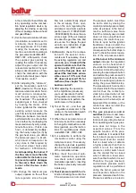
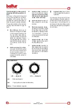
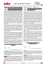
Stop indications
LFL …, Series 01
LFL …, Series 02
a-b
Start-up program
b-b’
“Trips” (without contact confirmation)
b(b’)-a
Post-ventilation program
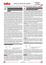
Control program in the event of
stopping, indicating position of
stop
As a rule, in the event of any kind
of stop, the fuel flow is cut off im
-
mediately. At the same time, the
programmer remains immobile, as
does the switch position indicator.
The symbol visible on the indicator
reading disk indicates the type of
fault.
◄
No start-up,
because of
failure in closing of a contact
or lock-out stop during or at
the end of the command se-
quence because of external
lights (for example: flames
not extinguished, loss at the
level of the fuel valve, defects
in the flame control circuit,
etc.)
▲
Start-up sequence stops
,
because the OPEN signal
was not sent to terminal 8
by limit switch contact “a”.
Terminals 6, 7 and 15 remain
powered until the defect is
eliminated.
P
Lock-out stop
, because of
lack of air pressure signal.
Any lack of pressure from
this moment onwards will
cause a lock-out stop!
▄
Lock-out stop
because of
flame detection circuit mal
-
function.
▼
Start-up sequence stops
,
because the position signal
for low flame was not sent to
terminal 8 by auxiliary switch
“m”. Terminals 6, 7 and 15
remain powered until the fault
is eliminated.
1
Lock-out stop
, due to lack
of flame signal at the end of
the first safety time.
2
Lock-out stop
, because no
flame signal was received at
the end of the second safety
time (main flame signal with
pilot burners at intermittent
operation).
▌
Lock-out stop
, due to lack
of flame signal during burner
operation.
If a lock-out stop occurs at any
moment between the start and pre-
ignition without a symbol, the cause
is generally to be attributed to a
premature or abnormal flame signal
caused, for example, by self-ignition
of a UV tube.
Summary of Contents for BGN 200 LX
Page 35: ...98 119 0006081062_200709...
Page 36: ...99 119 0006081062_200709...
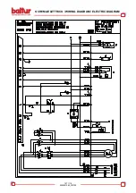
Page 44: ...107 119 0006081062_200709 SCHEMA ELETTRICO WIRING DIAGRAM ELECTRIC DIAGRAM...
Page 45: ...108 119 0006081062_200709 SCHEMA ELETTRICO WIRING DIAGRAM ELECTRIC DIAGRAM...
Page 46: ...109 119 0006081062_200709 SCHEMA ELETTRICO WIRING DIAGRAM ELECTRIC DIAGRAM...
Page 47: ...110 119 0006081062_200709 SCHEMA ELETTRICO WIRING DIAGRAM ELECTRIC DIAGRAM...
Page 48: ...111 119 0006081062_200709 SCHEMA ELETTRICO WIRING DIAGRAM ELECTRIC DIAGRAM...
Page 49: ...112 119 0006081062_200709 SCHEMA ELETTRICO WIRING DIAGRAM ELECTRIC DIAGRAM...
Page 50: ...113 119 0006081062_200709 SCHEMA ELETTRICO WIRING DIAGRAM ELECTRIC DIAGRAM...
Page 51: ...114 119 0006081062_200709 SCHEMA ELETTRICO WIRING DIAGRAM ELECTRIC DIAGRAM...
Page 52: ...115 119 0006081062_200709 SCHEMA ELETTRICO WIRING DIAGRAM ELECTRIC DIAGRAM...
Page 53: ...116 119 0006081062_200709 SCHEMA ELETTRICO WIRING DIAGRAM ELECTRIC DIAGRAM...
Page 54: ...117 119 0006081062_200709 SCHEMA ELETTRICO WIRING DIAGRAM ELECTRIC DIAGRAM...
Page 55: ...118 119 0006081062_200709 SCHEMA ELETTRICO WIRING DIAGRAM ELECTRIC DIAGRAM...
Page 56: ...119 119 0006081062_200709 SCHEMA ELETTRICO WIRING DIAGRAM ELECTRIC DIAGRAM...

