


47 / 119
0006081062_200709
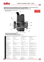
IGNITION AND GAS
REGULATION (METHANE)
1)
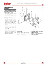
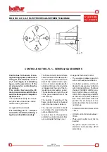
Make sure that the combus-
tion head penetrates into
the combustion chamber by
the quantity required by the
manufacturer.
Check that the
device that turning off the air
on the combustion head is in the
proper position for the required
fuel supply (the air passage
between disk and head must
be sensibly reduced in case of
low fuel supply. In the contrary
case, if the fuel supply is quite
high, the air passage between
disk and head must be opened).
See chapter “Combustion head
regulation”.
2) If not already done when con
-
necting the burner to the gas
pipes, taking the necessary
measures and opening doors
and windows, it is necessary
to bleed the air contained in
the pipes. Open the union on
the pipes close to the burner,
and slightly open the gas stop
cock(s). Wait until you smell the
typical gas smell, and then close
the cock. Wait for the necessary
time, according to the specific
conditions, until the gas present
in the room is dispersed outside
and then restore the connection
of the burner to the gas piping.
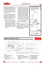
3)
Check that there is water in
the boiler and that the plant
dampers are open.
4)
Make sure that the combus-
tion product discharge can
occur freely (boiler and chim-
ney dampers open).
5) Check that the electrical line
voltage corresponds to that re-
quired for the burner, and that
the electrical connections (mo-
tor and main line) are preset
for the available voltage value.
Check that all electrical con
-
nections implemented on the
spot are properly executed as
per our wiring diagram.
6) Apply a pressure gauge with
suitable scale to the gas pres-
sure take-off to measure the
regulation value (if the expected
pressure rate allows it, it is pref
-
erable to use a water column
instrument,
do not
use hand
instruments for low pressures).
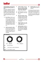
7) Regulate the air for the ignition
flame, for minimum flame and
high flame, following the instruc
-
tions for regulating air damper
control electrical motor shown in
the following pages
.
In practice,
set the low flame and high flame
air regulation cams to the suit-
able positions according to the
desired thermal power for low
and high flame.
8) By acting on the special
screw for adjusting the gas
and air pressure ratio, on the
gas valve
mod. MB-VEF..,
DMV-VEF.., set the desired
value (see the specific instruc
-
tions for the gas valve MB-VEF..,
DMV-VEF.. in the following
pages).
9) With the burner panel switch set
to “0” and main circuit breaker
on, manually turn the contactor
off and check that the motor runs
in the correct direction. If nec-
essary, invert the place of two
cables of the line supplying the
three-phase motor to reverse
the direction of rotation
.
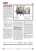
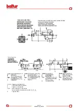
10)
I n s t r u c t i o n s f o r m a n u a l
mode working of the burner
Combustion control can be
carried out over the whole mo
-
dulation range while manually
controlling the MPA 22 equip-
ment. For this use modulation
connector (B) in the diagram,
which is provided with the burner
as standard. After disconnecting
the 4-pole plug (A) which takes
the signals from the thermostat
or the RWF 40 adjustor, insert
the connector in position (B).
Use the +/- buttons to increase
or reduce the gas and air supply.
After this control, put the 4-pole
plug (A) back in so as to reset
automatic mode modulation.
Note
:
Pre-ventilation is carried out
with open air and thus, dur
-
ing the same, the regulation
servomotor is enabled, and it
runs a complete opening stroke
up to the “maximum” set. Only
when the regulation servomotor
returns to the “ignition” position,
the control box continues its
ignition program by enabling
the transformer and the ignition
gas valves.
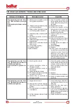
During the pre-ventilation step,
make sure that the air pressure
control switch changes position
(from off position without pressure
detection it must switch to the off
position with air pressure detec
-
tion). If the air pressure switch
does not detect the sufficient pres
-
sure (it does not switch position),
the ignition transformer and the
flame gas valves are not enabled,
and thus the control box “locks”.
To “unlock”, press the “unlock” push
button(8). At the first stage there
may occur further “locks” due to:
a) The gas pipes have not been
sufficiently air-bled, and thus the
gas quantity is not sufficient to
allow a stable flame.
b) The “lock” with presence of flame
may be caused by instability of
the same in the ionisation zone
for an incorrect air/gas ratio.
Remedy is by varying the quan
-
tity of supplied air and/or gas so
as to find the correct ratio. The
same problem may be caused
by a wrong air/gas distribution
Summary of Contents for BGN 200 LX
Page 35: ...98 119 0006081062_200709...
Page 36: ...99 119 0006081062_200709...
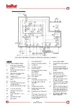
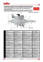
Page 44: ...107 119 0006081062_200709 SCHEMA ELETTRICO WIRING DIAGRAM ELECTRIC DIAGRAM...
Page 45: ...108 119 0006081062_200709 SCHEMA ELETTRICO WIRING DIAGRAM ELECTRIC DIAGRAM...
Page 46: ...109 119 0006081062_200709 SCHEMA ELETTRICO WIRING DIAGRAM ELECTRIC DIAGRAM...
Page 47: ...110 119 0006081062_200709 SCHEMA ELETTRICO WIRING DIAGRAM ELECTRIC DIAGRAM...
Page 48: ...111 119 0006081062_200709 SCHEMA ELETTRICO WIRING DIAGRAM ELECTRIC DIAGRAM...
Page 49: ...112 119 0006081062_200709 SCHEMA ELETTRICO WIRING DIAGRAM ELECTRIC DIAGRAM...
Page 50: ...113 119 0006081062_200709 SCHEMA ELETTRICO WIRING DIAGRAM ELECTRIC DIAGRAM...
Page 51: ...114 119 0006081062_200709 SCHEMA ELETTRICO WIRING DIAGRAM ELECTRIC DIAGRAM...
Page 52: ...115 119 0006081062_200709 SCHEMA ELETTRICO WIRING DIAGRAM ELECTRIC DIAGRAM...
Page 53: ...116 119 0006081062_200709 SCHEMA ELETTRICO WIRING DIAGRAM ELECTRIC DIAGRAM...
Page 54: ...117 119 0006081062_200709 SCHEMA ELETTRICO WIRING DIAGRAM ELECTRIC DIAGRAM...
Page 55: ...118 119 0006081062_200709 SCHEMA ELETTRICO WIRING DIAGRAM ELECTRIC DIAGRAM...
Page 56: ...119 119 0006081062_200709 SCHEMA ELETTRICO WIRING DIAGRAM ELECTRIC DIAGRAM...