8
english
4.1
Design
1
2
3
4
1
3 × 7-segment display (yellow)
2
4 × 7-segment display (orange)
3
Status LEDs (PWR/OUT/NC)
4
Menu buttons
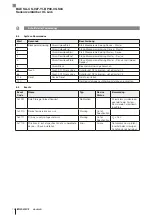
Fig. 4-1: Product view, operating and display elements
4
Product description
4.2
Function
The sensor amplifier works as a base unit for a special
series of capacitive sensors (half variants without their own
switching power amplifiers, especially mini and high-
temperature sensors). The sensors detect objects or fill
levels, for example, and forward the information to the
amplifier. Operation in a control loop uses the entire
working range of the sensors. Further signal processing
takes place in a microprocessor.
The software periodically records the control voltage and
uses it to generate a switching signal, which is emitted at
the output. Principally, the parameters are available via
IOLink. In standard mode, all settings are possible on the
device as well.
The following parameters can be adjusted:
– Switching power amplifier in SIO mode: PNP, NPN,
push-pull, N.O., N.C.
– Adjustment or automatic teach-in of the sensor sensiti-
vity to the switching distance application
– Remotely triggered, situational teach-in of sensor
sensitivity to application (via a fourth program line)
– Different switching modes with one or two switchpoints
– Switch on and off times
– Dynamic operation
– Detection of only moved objects
– Permanent, slow background suppression
The amplifier is operated via menu settings (buttons and
display) or the IO-Link interface.
If connected to an IO-Link master, the display shows
I OL
.
Without IO-Link master, the device works in SIO mode
(serial input/output) and behaves like a product with a
standard output power amplifier.
The output is protected against overcurrent and short
circuits. The limit values for overcurrent (approx. 200 mA)
and for overheating are fixed settings. An overcurrent/short
circuit error is indicated on the display with
E r r out p
.
4.3
Operating and display elements
Element
Funktion
888
Display
(yellow)
Displays the brief description of
the menu item. If connected to an
IO-Link master,
I
OL
is displayed.
8888
Display
(orange)
Displays the parameters as a
numerical value or in the form of a
selection
PWR
LED
(green)
Lights up when operating voltage
is applied
OUT
LED
(yellow)
Indicates the actuated switching
tate (dependent on the set
configuration
N.C./N.O.
)
NC
LED (red)
Does not light up if no operating
voltage is applied or
N.O.
is
configured.
Lights up when operating voltage
is applied and
N.C.
is configured.
Button
Browse further through menu
item or increase value range
If the button is pressed for an
extended period of time, a rapid
scroll of values is activated.
Button
Browse back through menu item
or lower value range
If the button is pressed for an
extended period of time, a rapid
scroll of values is activated.
Button
Activate parameter input within
menu item
Button
Save value range selection,
teach-in, start/save, jump to
submenu selection from
[ ]conF
and
[ ]di SP
Tab. 4-1: Operating and display elements
BAE SA-CS-027-YI-BP00,3 GS04
IO-Link Sensor Amplifier
Summary of Contents for IO-Link BAE SA-CS-027-YI-BP00,3 GS04
Page 1: ...BAE SA CS 027 YI BP00 3 GS04 deutsch Betriebsanleitung english User s guide ...
Page 2: ...www balluff com ...
Page 3: ...BAE SA CS 027 YI BP00 3 GS04 Betriebsanleitung deutsch ...
Page 4: ...www balluff com ...
Page 26: ......
Page 27: ...BAE SA CS 027 YI BP00 3 GS04 User s Guide english ...
Page 28: ...www balluff com ...


