background image

Care2
Installation Instructions

58

Care2 issue 7

5.2  SD C

ARD

 C

ONFIGURATOR

The SD Card Configurator has four pages, and each page is 
described in the following sections.

5.2.1  SD Card “ConsoleConfig” Page

This shows Configuration Data for the selected Console.

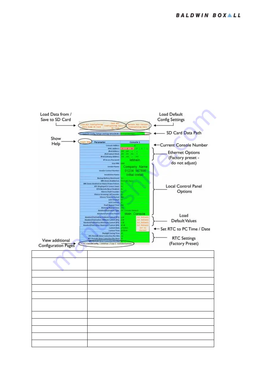
Figure 5.1 — SD ConsoleConfig Page - Console Configuration Details

Title

Description

Load Data from / Save to SD 
Card

Buttons allow the operator to load a Configuration from the SD 
Card, and to save the current Configuration to the SD Card 

Show Help

Shows (or hides) the Help view

View Additional Config Pages Switches to show additional Configuration Pages
Load Default Config Settings Loads Default settings for ALL Console & Handset options
SD Card Data Path

Displays the current path for SD Card Loading / Saving 

Current Console Number

Shows the Console Number for the Data being displayed:


Select the required Console from the dropdown menu

Ethernet Options

Factory Preset (Do not adjust - sets the address for connecting via IP)

Local Console Options

Settings for the Local Console

Load Default Values

Load Default options for Handset Monitoring

Set to Current RTC

Load Real Time Clock settings from the PC

RTC Settings

Real Time Clock Settings (Factory Preset) 

www.acornfiresecurity.com

www.acornfiresecurity.com

Summary of Contents for C2CFPE

Page 1: ...Care2 Installation Instructions Firmware version MCCNTPNL V 03 04 Manual name Care2 Issue 7 ECR 2853 Date of issue July 2014 www acornfiresecurity com www acornfiresecurity com ...

Page 2: ...one Sockets 7 Simplified Schematic Diagrams____________________________8 Installation Consoles __________________________________________11 Mounting Details 11 C2CEK4 Line Card Connection Details 12 Adding C2CEK4 Line Cards ____________________________13 Installing C2CFPE Interface Card_________________________16 Installing C2CN Network Card__________________________19 Setting Network Address 21 N...

Page 3: ...____________ 34 Commissioning Basic Hardware Commissioning Procedure _________________ 35 Master Slave NEP Indicator __________________________ 37 Master or Non networked Console 37 Slave Console 37 NEP Console 37 Software Commissioning Procedures _____________________ 38 Initial Commissioning using SD CARD 38 Commissioning Using Ethernet IP Method 40 Internal Device Detection Procedure __________...

Page 4: ...P IP Configuration Windows XP 63 Setting Alternate TCP IP Configuration Windows 7 66 IP Configuration ConsoleConfig Page 69 IP Configuration LineSetups Page 70 IP Configuration Logs Page 70 IP Configuration OutstationSummary Page 70 Operation Accept a Single Incoming Call ___________________________71 Multiple Incoming Calls________________________________72 Selecting a Single Call 72 Selecting Al...

Page 5: ...______________________ 81 Battery Charger Local Console Fault 81 Power Supply Local Console Fault 81 System Restart xx Local Console Fault 81 Local Loop Local Console Fault 82 Lo Z Line Fault Local Console Fault 82 Hi Z Line Fault Local Console Fault 82 NW Audio Loop Network Audio Fault 82 NW Loop Network Data Fault 82 Deep Discharge Low Voltage Protection 82 Routine Maintenance Requirements _____...

Page 6: ... Communications Limited In the interest of continual product development Baldwin Boxall Communications Limited reserves the right to make changes to product specification without notice or liability Use of Baldwin Boxall Communications Limited products as critical components in life support systems is not authorised except with express written approval from Baldwin Boxall Communications Limited Ch...

Page 7: ...utions Personnel who install maintain or repair this equipment must read the safety information below before starting work AC Supply Voltage 230V 10 RMS 50Hz AC DC Supply Voltage 21V to 27 6V Nominal 24V DC Temperature Operating Storage 5 C up to 40 C Humidity Range IP Rating 0 90 Non Condensing IP30 CAUTION This product must only be disposed of in accordance with the WEEE directive WARNING This e...

Page 8: ...l are considered hazardous and the external wiring connected to these terminals requires installation by suitably trained personnel WARNING Note that this equipment uses battery backup and if the Mains Supply is disconnected Hazardous voltages will still be accessible on the terminals marked with the High Voltage symbol WARNING Always replace blown fuses with the correct type and rating If a fuse ...

Page 9: ...Care2 Installation Instructions x Care2 issue 7 www acornfiresecurity com www acornfiresecurity com ...

Page 10: ...rk Expansion Panels and the Outstations The Outstations and Fire Emergency Telephones are supplied in different styles to suit any installation The Care2 system is radial or Star Wired to each Outstation with Power Audio transmitted on a single pair of conductors Each Care2 Console can address four Outstations by default and this can be increased to a maximum of 16 Outstations by fitting additiona...

Page 11: ...per Outstation Front Panel Indicators LCD Matrix Display Rotary Encoder for System Control LEDs Power Incoming Call Refuge Areas Active System Healthy Processor Restart Common Fault Processor Fault Remote Signalling of Fault Volt free contact closing opening set at installation Dimensions W X H x D 430mm x 310mm 7U x 130mm Bezel Dimensions W x H 470mm x 350mm Weight 14Kg with batteries Bezel Cutou...

Page 12: ...prox 50mA per Remote Unit Front Panel Indicators LCD Matrix Display Rotary Encoder for System Control LEDs Power Incoming Call Refuge Areas Active System Healthy Processor Restart Common Fault Processor Fault Remote Signalling of Fault Volt free contact closing opening set at installation Dimensions W X H x D 430mm x 310mm 7U x 130mm Bezel Dimensions W x H 470mm x 350mm Weight 14Kg with batteries ...

Page 13: ...on Internal Control Volume Control Power Supply 16 20V DC Current Consumption 1 5mA 16V 0 03W Standby 40mA 10V 0 4W Active Dimensions W X H x D 134mm x 134mm x 48mm Front panel backbox Bezel Dimensions W x H 154mm x 154mm 10mm radius Bezel Cutout W x H x D 136mm x 136mm 10mm radius Knockouts 20mm and 25mm diameter in sides of backbox Weight 0 75 Kg Temperature Range 10 to 40 C storage and operatin...

Page 14: ...ator System OK Power Supply 16 20V DC Current Consumption 1 5mA 16V 0 03W Standby 40mA 10V 0 4W Active DImensions W X H x D 130mm x 330mm x 75mm Front panel backbox Bezel Dimensions W x H 170mm x 370mm Bezel Cutout W x H x D 136mm x 336mm x 80mm Knockouts 1 x 20mm diameter in top of backbox Weight 2 2 Kg Temperature Range 10 to 40 C storage and operating www acornfiresecurity com www acornfiresecu...

Page 15: ...ght Sounder Reset Point Ceiling Pull Cord W X H x D 85mm x 85mm x 58mm excluding back box 85mm x 85mm x 13mm excluding back box 87mm diam x 30mm including surface mount enclosure Back Box requirements Over Door Light Sounder Reset Point Ceiling Pull Cord Back boxes are not supplied with the DTA Kit 25mm deep single gang flush box or round cornered plastic surface box is required 25mm deep single g...

Page 16: ...closures Power Consumption 1 5mA 16V 0 03W per monitored handset Dimensions W X H x D 430mm x 310mm 7U x 130mm Bezel Dimensions W x H 470mm x 350mm Bezel Cutout W x H x D 440mm x 320mm x 135mm Knockouts 20mm diameter x 23 in top only Security Handsets stored behind lockable door Weight 6 2Kg 0 35Kg per handset Temperature Range 10 to 30 C storage and operating Humidity Range 95 Non Condensing www ...

Page 17: ...tations can be fitted to the Care2 Console as shown in Figure 1 8 The system is Star Wired with each Outstation connected using its own pair of wires NOTE Fire Rated screened cable should be used If Fire Rated cable is not used then screened cable is recommended to ensure the best audio quality www acornfiresecurity com www acornfiresecurity com ...

Page 18: ...Typical Network Schematic Diagram NOTE Each Console and NEP can have a maximum 16 Outstations attached Upto 15 NEPs can be networked together or 14 using a Master a Slave Consoles to allow upto 256 Outstations www acornfiresecurity com www acornfiresecurity com ...

Page 19: ...Care2 Installation Instructions 10 Care2 issue 7 www acornfiresecurity com www acornfiresecurity com ...

Page 20: ...wo being a keyhole design that enables quick and simple mounting Ensure all four mounting points are used to mount the console securely to the wall surface Figure 2 1 Console Mounting Holes WARNING Ensure the wall surface is strong enough to support the weight of the console 14Kg including batteries www acornfiresecurity com www acornfiresecurity com ...

Page 21: ...tar Wired to the console with each Outstation having its own pair of conductors Figure 2 2 Line Card Site Wiring Connections The termination blocks on the Line Card are Cage Clamp terminals to enable quick and secure connections NOTE Fire Rated screened cable should be used If Fire Rated cable is not used then screened cable is recommended to ensure the best audio quality www acornfiresecurity com...

Page 22: ... isolated 2 Remove the 4 off M3x10 screws securing the front door of the Console Figure 2 4 Remove 4 x Front Panel Screws 3 Carefully open the hinged door 4 Disconnect and isolate the battery backup supply 5 Carefully undo the M4x8 screw holding the cable loom the screw will be held captive by the cable tie base WARNING Before attempting to fit this component ensure the Mains Power Supply and Batt...

Page 23: ...nk cable from the first Line Card and connect the BLUE RJ45 cable to the Uplink connection on the new Line Card as shown in Figure 2 7 8 Fit the Red Link Cable between the Uplink connector on the original Line Card and the Downlink connector on the new Line Card Figure 2 7 New C2CEK4 Line Card Installed and Connected The New Line Card is now installed and ready for connection to the Site Cabling s...

Page 24: ...loosening the cable loom mount Figure 2 8 Console with Three Line Cards Fitted Figure 2 9 Console with Four Line Cards Fitted NOTE Before the new C2CEK4 Line cards can be used the Device Detection procedure must be followed See section 4 4 on page 43 for details www acornfiresecurity com www acornfiresecurity com ...

Page 25: ...et contacts Figure 2 10 Typical C2CFPE Expansion Line Card 1 Ensure the Mains 230V supply is isolated 2 Remove the 4 off M3x10 screws securing the front door of the Console Figure 2 11 Remove 4 x Front Panel Screws 3 Carefully open the hinged door 4 Disconnect and isolate the battery backup supply 5 Fit the C2CFPE unit to the left of the first line card using the M4x8 screws provided WARNING Befor...

Page 26: ...re 2 13 Figure 2 13 Yellow RJ45 Cable connected to C2CFPE 7 The YELLOW RJ45 cable should be connected to the FIRE PANEL connection on the Front Panel board Figure 2 14 C2CFPE Connection to Front Panel 8 Secure the green and yellow cables to the existing loom using the cable ties provided Figure 2 15 Recommended cable tie positions www acornfiresecurity com www acornfiresecurity com ...

Page 27: ... enable the Fire Panel input set the DRS Enable option in the System Menu to N Closed see Section 4 9 1 on page 55 NOTE In a Networked System with a Master and a Slave console BOTH must have a C2CFPE module fitted The Fire Panel connections and Remote Enable Switch if required must be connected to both the Master and Slave consoles www acornfiresecurity com www acornfiresecurity com ...

Page 28: ...igure 2 18 Typical C2CN Network Card 1 Ensure the Mains 230V supply is isolated 2 Remove the 4 off M3x10 screws securing the front door of the Console Figure 2 19 Remove 4 x Front Panel Screws 3 Carefully open the hinged door 4 Disconnect and isolate the battery backup supply WARNING Before attempting to fit this component ensure the Mains Power Supply and Battery Backup have been disconnected as ...

Page 29: ...LLOW RJ45 cable to the FIRE PANEL connector as shown in Figure 2 21 Figure 2 21 C2CN Fire Panel Connection details 7 Move the WHITE RJ45 cable from the Line Card to the DOWNLINK connector on the network card Figure 2 22 Network Downlink Connection 8 Fit the short RED RJ45 between the Network Card UPLINK connector and the Line Card DOWNLINK connector www acornfiresecurity com www acornfiresecurity ...

Page 30: ...ions to Front Panel 2 4 1 Setting Network Address 1 Clear Device Assignments refer to Section 7 6 on page 81 2 Set the Network Address refer to Section 4 9 on page 55 3 Perform the Internal Device Detection Procedure refer to Section 4 4 on page 43 and ensure it is successful NOTE The Network Address is normally set during Commissioning To manually set the Network Address use this procedure NOTE N...

Page 31: ... as a loop with 2 x 2 Core Fire Rated Cables a Data pair and an Audio pair between the Master Console and each Network Expansion Panel The maximum cable distance between each Console is 500m NOTE Ensure the Network Address has been Manually Set on all Network Panels refer to Section 2 4 1 for details www acornfiresecurity com www acornfiresecurity com ...

Page 32: ... Sounders in CCT To enable the Fire Panel input set the DRS Enable option in the System Menu to N Closed see Section 4 9 1 on page 55 NOTE In a Networked System with a Master and a Slave console both will have a C2CN module fitted The Fire Panel connections and Remote Enable Switch if required must be connected to both the Master and Slave consoles www acornfiresecurity com www acornfiresecurity c...

Page 33: ... Output settings 2 5 1 External Call Settings using BVOCCA If a BVOCCA Call Alert Module is used P15 must be set to N O and P16 set to 24V The connections to the C2CN and C2CFPE are shown below Figure 2 29 BVOCCA Connection details NOTE The Console must be fitted with either a C2CN or C2CFPE to access the External Call terminations The External Call output is available on the following Consoles C2...

Page 34: ... Termination block on the DRS Refuge Remote as shown in Figure 2 31 Figure 2 31 DRS Refuge Remote Connection Details The termination blocks on the DRS unit are Cage Clamp terminals to enable quick and secure connections The Loop Amplifier output is an audio feed that can be used as an input to a separate Induction Loop amplifier www acornfiresecurity com www acornfiresecurity com ...

Page 35: ...s Figure 2 32 Mounting Holes for Fire Stewards Telephone 2 7 2 Connection Details Figure 2 33 Site Wiring Connections for Fire Stewards Telephone The termination blocks on the DRS unit are Cage Clamp terminals to enable quick and secure connections www acornfiresecurity com www acornfiresecurity com ...

Page 36: ...SABLED TOILET ALARM 2 8 1 Mounting Details Figure 2 34 DTAKIT Installation Instructions NOTE The Over Door Light DTAODL and Reset Point DTARP should be installed in suitable back boxes Back Boxes are not supplied www acornfiresecurity com www acornfiresecurity com ...

Page 37: ...nsole and the Over Door Light should be wired using Fire Rated two core cable The connections between the Over Door Light the Reset Panel and the Ceiling Pull Cord should be wired using suitable Security Alarm Cable Figure 2 35 DTAKIT Connection Details www acornfiresecurity com www acornfiresecurity com ...

Page 38: ...ing Connections for Jack Socket The termination blocks on the Jack Socket Plate are Cage Clamp terminals to enable quick and secure connections The Jack Socket Plates are supplied with a 10KΩ termination resistor fitted This resistor must be fitted to enable the Console to detect and monitor the jack socket NOTE If multiple jack sockets are connected in a daisy chain arrangement then the terminati...

Page 39: ...Care2 Installation Instructions 30 Care2 issue 7 www acornfiresecurity com www acornfiresecurity com ...

Page 40: ...CD Display shows the current status of the system indicates incoming calls and can be used for basic configuration The Encoder is used to scroll through the menu to Make or Answer Calls see section 6 1 on page 71 make Configuration changes see section 4 6 on page 49 and accept faults see section 7 1 on page 79 www acornfiresecurity com www acornfiresecurity com ...

Page 41: ...en Panel has either 24V Battery or Mains Supply Incoming Call Flashes to indicate Incoming Call Refuge Areas Active Illuminates when DRS Refuge Remotes are active System Healthy Illuminates when no Faults are present Processor Restart Fault Illuminates after the Processor has restarted Common Fault Illuminates if any fault is detected Processor Fault Illuminates if the system detects a Processor f...

Page 42: ...sioning to ensure the volume level is suitable for the installation Ident Description Status Red LED Steady ON Currently making a call Flashing with ringtone unit is being called System OK Green LED Flashing every 5 seconds System in Standby Steady ON System Active Ready for use Call Accept Button Press once to make a call or accept an incoming call www acornfiresecurity com www acornfiresecurity ...

Page 43: ...dicator The Status LED illuminates to show the unit is powered and ready for use The LED will extinguish when the door is opened 3 7 ROAMING HANDSET ENCLOSURE Figure 3 7 Roaming Handset Status LEDs The Handset Status LEDs indicate each handset is powered and ready for use www acornfiresecurity com www acornfiresecurity com ...

Page 44: ...Network card if required Refer to Section 2 2 Section 2 3 and Section 2 4 page 13 page 23 for installation details 2 Connect the Outstations to the Line Cards see Section 2 1 2 on page 12 3 Apply Power using either Mains or the internal Batteries 4 Clear Device Assignments see Section 7 6 on page 81 5 While the Control Panel is booting up initiate the Internal Device Detection procedure see Sectio...

Page 45: ...e audio path is correct NOTE It is possible to perform the basic functionality check on NEP Consoles if a Roaming Handset C2RTH is plugged into the front panel The NEP will automatically detect the C2RTH Handset and allow the console to answer incoming LOCAL calls On removal the NEP will announce a fault as the handset is being monitored The Console Handset must be changed to None after testing is...

Page 46: ...sole NOTE If a C2CN Network is detected the default is Slave console otherwise the default setting is Master console Note After completing the Internal Device Detection procedure select option 3 as shown above on the Master Console The Master and Slave Consoles are toggled using this option NOTE This option is automatically selected if CH Type None is entered into the Console configuration and a H...

Page 47: ...Console 1 is selected on the ConsoleConfig Page Complete the Configuration details for the Master Console see Section 5 2 1 on page 58 7 Save the spreadsheet identifiable as the Master Console spreadsheet to a known location as this contains the configuration data for all the outstations and the settings specific to the Master Console 8 Select the Save ALL Config Data to SD Card option see Section...

Page 48: ...t identifiable as the relevant Slave or NEP console to a known location as this contains the configuration data for all the outstations and the settings specific to the Relevant Console 9 Select the Save ALL Config Data to SD Card option see Section 5 2 6 on page 61 10 Using the USB options on the PC eject the SD Card to enable safe removal of the device then remove the SD Card 11 Ensure the Conso...

Page 49: ...sole see Section 5 2 2 and Section 5 2 3 on page 59 6 Ensure the Master Console Console 1 is selected on the ConsoleConfig Page Complete the Configuration details for the Master Console see Section 5 2 1 on page 58 7 Save the spreadsheet identifiable as the Master Console spreadsheet to a known location as this contains the configuration data for all the outstations and the settings specific to th...

Page 50: ...ole Address select the relevant Console Number see Section 5 3 4 on page 69 6 Complete the Configuration details for the Slave or NEP Console see Section 5 3 4 on page 69 7 Save the spreadsheet identifiable as the relevant Slave or NEP console to a known location as this contains the configuration data for all the outstations and the settings specific to the Relevant Console 8 Select the Connect a...

Page 51: ...nd ensure it is successful 12 Connect the local Network Connections see Section 2 4 2 on page 22 to the network card 13 Repeat steps 1 to 12 for the Slave all NEP Consoles Note Perform a System Reset on the MASTER Control Panel after all other panels are configured and connected www acornfiresecurity com www acornfiresecurity com ...

Page 52: ... Detection Mode as shown in Figure 4 5 Figure 4 5 LCD Display showing Device Detection NOTE Always Clear Device Assignments see Section 7 6 on page 81 before running the Device Detection Procedure NOTE This procedure is necessary during Commissioning if a Line Card C2CKE4 or a Network Card C2CN has been added or if a faulty card is replaced within the Console This procedure also writes the Network...

Page 53: ...stem Reset and continue with the Commissioning procedure Figure 4 7 Device Detection Failure If the Device Detection failed then check all connections between the Front Panel and the Line Cards including Link Leads and ensure the Uplink Downlink cables are connected correctly Restart the Device Detection Procedure after checking all Connections NOTE The C2CN Network card must be DISCONNECTED from ...

Page 54: ... and displays the Main Menu as shown in Figure 4 9 Figure 4 9 Display showing Main Menu 3 Press the encoder to select the System option Figure 4 10 Enter PIN number The system will ask for a PIN number The default PIN is 0000 NOTE When the Console boots up this procedure is performed automatically and the Console will ADD new Outstations Manually initiating this procedure enables the Console to RE...

Page 55: ...he Line Parameters Menu will be displayed Figure 4 13 Console Selection Option Shown on Master Console Only Figure 4 14 Typical Line Parameters Menu Local Console selected NOTE On the Master Console in a networked system there is an extra screen showing all consoles on the system and the operator can choose which console is to be selected Consoles with configuration information are shown with a ww...

Page 56: ...h line in turn If a new Outstation is found the Console will store the data in the Line Parameters menu If a previously detected Outstation is not found then the Manually Selected Auto Assign process will replace the outstation type with N A NOTE The Auto Assign procedure can only be initiated on the Local Console NOTE At any time it is possible to Escape to the Exit Entry in the current menu by P...

Page 57: ... Menu and ensure the number of Outstations found matches the number of Remote Units installed on the system If any Remote Units are missing from the list then the connections between the Console and the Remote Unit s should be checked for continuity The Auto Assign Procedure should then be repeated 11 When complete select Exit to return to the System Menu www acornfiresecurity com www acornfiresec...

Page 58: ...ailable Icons are Console Handset Stewards Telephone Fire Telephone Disabled Refuge Remote Disabled Toilet Alarm x1 Single Pullcord Disabled Toilet Alarm x 2 Dual Pullcords Roaming Telephone Jack Socket Roaming Telephone Enclosure Disable Refuge with Firephone Future Use 3 Scroll up or down to highlight the Icon suitable for the Remote Unit in use 4 Press the Encoder to store the correct Icon NOTE...

Page 59: ...e correct Outstations identified on each Line The Console uses this information to configure the features and functions available for the different types of Outstation If DTA x2 is selected the EOLz OC End Of Line Impedance Open Circuit value is automatically adjusted to monitor Two Units If the Roaming Handset Enclosure is selected the EOLz OC value must be entered manually see Section 4 8 on pag...

Page 60: ...rameters for Outstation 1 2 Scroll down until the name is selected and press the encoder Figure 4 21 Current Name of Line 1 Highlighted Scroll up and down to change each character in turn and press the encoder to move onto the next character Figure 4 22 Renaming Line 1 NOTE The Outstation Names are normally specified during the SD or IP Configuration This procedure shows how to manually change the...

Page 61: ...e changes made 4 7 1 ASCII Character Set Figure 4 24 ASCII Character Set showing Character Order Figure 4 24 shows the order of the characters when the encoder is turned Clockwise The DEL character when selected allows the operator to go back a single character to change it NOTE To Exit without saving the changes select Exit Without Save and press the encoder www acornfiresecurity com www acornfir...

Page 62: ... page 45 to open the Line Parameters menu Figure 4 25 Line Parameters Menu showing Lines 1 4 2 Scroll up or down to highlight the Line with the Enclosure Line 2 in this example Figure 4 26 Highlight the Required Line 3 Press the encoder and the parameters for that Line will then be displayed Figure 4 27 Parameters for Line 2 4 Scroll down until EOLz OC End Of Line Impedance Open Circuit value is s...

Page 63: ...closure Table 4 1 End Of Line Values for Handset Enclosure 6 When the EOL Value is correct for the number of handsets in use press the encoder 7 Scroll down to Save and Exit 8 Press the encoder to save the changes and exit the Line 2 Menu Number of Handsets Stored in Enclosure Required EOL OC Value 1 400uA 2 1300uA 3 2150uA 4 3050uA 5 3900uA 6 4800uA www acornfiresecurity com www acornfiresecurity...

Page 64: ...ly Open DRS PF Enable Yes Enable DRS Remote Units on Mains Power Failure RTC in ScnSvr No Show Real Time Clock on ScreenSaver Fault Silence No Temporarily disable Fault Sounder IC Call Silence No Temporarily disable Incoming Call Sounder Silence Timeout 480mins Timeout before Fault Incoming Call Sounders are reactivated LCD Timeout 60secs Timeout for LCD to return to Screensaver LCD Contrast 37 LC...

Page 65: ...n is detected To ensure correct operation the Installer must select the type of Outstation attached to the Line Name Outstation n Name of the Outstation Ln Offhook 1 6400uA Threshold for Outstation Offhook Ln Onhook 1 9600uA Threshold for Outstation Onhook Ln EOLz OC 1 400uA Threshold for Open Circuit Outstation Fault CH EOLz SC 1 48800uA Threshold for Short Circuit Outstation Fault Restore Defaul...

Page 66: ... data each Console SD Card is different and also data for the outstations on the system Both SD IP Configurators are based on a Microsoft Excel Spreadsheet and this application is required to open the files NOTE Only SD Cards correctly formatted by a Console can be used to store Configuration Data The SD cards can be read and written by PCs but use a specific FAT16 file format that is different to...

Page 67: ... View Additional Config Pages Switches to show additional Configuration Pages Load Default Config Settings Loads Default settings for ALL Console Handset options SD Card Data Path Displays the current path for SD Card Loading Saving Current Console Number Shows the Console Number for the Data being displayed Select the required Console from the dropdown menu Ethernet Options Factory Preset Do not ...

Page 68: ...a only has to be entered once regardless of how many Consoles or Outstations are in use as the relevant information is downloaded to the Console 5 2 3 To Enter Handset Outstation Data 1 Select Console 1 from the Dropdown Menu on the ConsoleAddress page This ensures that Console 1is at the top of the list on the LineSetups page Figure 5 3 Selecting Console 1 on the ConsoleAddress Page 2 Switch to t...

Page 69: ...ole 1 Line 2 select the type of Outstation in use from the Dropdown Menu Figure 5 6 Selecting Type of Outstation for Console 1 Line 2 6 Double click in the box below to rename the Outstation Figure 5 7 Renaming Console 1 Outstation 2 7 Repeat steps 3 to 6 for each Outstation on the system including those connected to all other Consoles 8 When all outstations have been entered into the Configurator...

Page 70: ...n on the ConsoleConfig page All current configuration data will be overwritten 5 2 6 Saving Configuration to an SD Card To Save the current configuration to the SD Card press the Save ALL Config Setup button on the ConsoleConfig page Figure 5 8 Selecting Console 1 on the ConsoleAddress Page NOTE If the CONFIG__ DAT file cannot be found on the SD Card then it is not correctly formatted and cannot b...

Page 71: ... from the SD Card This will overwrite the data currently shown Press the Clear Even Fault Log file on the SD Card button to clear the fault log currently stored on the SD Card Press the Clear Log Table to clear the data being displayed Figure 5 9 Typical Fault Log 5 2 8 OutstationSummary Page The OutstationSummary Page of the Configurator shows the operator the Outstations that are set up on the S...

Page 72: ...ation without making any changes to the existing TCP IP Configuration The following sections give basic instructions on setting this alternate Configuration using Windows XP and Windows 7 5 3 2 Setting Alternate TCP IP Configuration Windows XP 1 Open the Windows XP Control Panel and open the Network Connections tab Figure 5 11 Typical Windows XP Network Connections 2 Under the LAN or High Speed In...

Page 73: ...elect Properties Figure 5 13 Local Area Connection Internet Protocol TCP IP Selected 4 The Internet Protocol TCP IP Properties will be displayed with the General tab showing Select the Alternate Configuration tab Figure 5 14 Internet Protocol Properties General Settings Displayed 5 In the Alternative Configuration Tab select User configured and enter the following details www acornfiresecurity com...

Page 74: ...et Mask 255 255 252 0 Note this is NOT the auto setting Default Gateway 192 168 2 254 Figure 5 15 User Configured Alternate Configuration 6 Select OK and the Properties box will close Close the Local Area Connection Dialog box www acornfiresecurity com www acornfiresecurity com ...

Page 75: ...bove and the Network Adaptors installed on the PC will be displayed 3 Double click on the Local Area Connection icon Figure 5 17 Local Area Connection Icon 4 The status of the Local Area Network will be displayed Select Properties as shown below Figure 5 18 Local Area Network Connection Status 5 The Local Area Connection Properties will then be displayed Highlight Internet Protocol Version 4 TCP I...

Page 76: ...e Alternate Configuration tab Figure 5 20 Internet Protocol Properties General Settings Displayed 7 Inthe Alternative Configuration Tab select User configured and enter the following details IP address 192 168 2 1 Subnet Mask 255 255 252 0 Note this is NOT the auto setting Default Gateway 192 168 2 254 Un check the Validate settings if changed upon exit box www acornfiresecurity com www acornfires...

Page 77: ...Configuration 8 Select OK and the Properties box will close Close the Local Area Connection Dialog box Note The Windows Network Diagnostics window may appear simply press Close the troubleshooter as the network settings cannot be checked www acornfiresecurity com www acornfiresecurity com ...

Page 78: ... Help Shows or hides the Help view View Additional Config Pages Switches to show additional Configuration Pages Load Default Config Settings Loads Default settings for ALL Console Handset options Current Console Number Shows the Console Number for the Data being displayed Select the required Console from the dropdown menu Ethernet Options Factory Preset Do not adjust sets the address for connectin...

Page 79: ...ibed in Section 5 2 2 and Section 5 2 3 5 3 6 IP Configuration Logs Page The IP Logs page is almost identical to the SD Card version as described in Section 5 2 7 5 3 7 IP Configuration OutstationSummary Page The IP OutstationSummary page is almost identical to the SD Card version as described in Section 5 2 8 www acornfiresecurity com www acornfiresecurity com ...

Page 80: ...the LCD Backlight Display will flash The LCD Display will indicate the Outstation making the call Figure 6 1 LCD Display showing a Single Incoming Call Open the Handset Door and pick up the handset Press the Encoder to accept the call and speak to the caller Figure 6 2 LCD Display showing Outstation 3 Busy In Conversation www acornfiresecurity com www acornfiresecurity com ...

Page 81: ...en the Handset Door and pick up the handset Scroll up or down until the required Outstation is Highlighted Press the Encoder to answer the selected call The LCD Display will indicate the Answered Call and also show the other caller is still calling as shown in Figure 6 4 Figure 6 4 LCD DIsplay showing Answered and Waiting Calls NOTE The Console Incoming Call LED Sounder are silenced while a Call i...

Page 82: ...D Display showing All Answer with Multiple Calls Press the encoder to answer All Incoming Calls and speak to All Outstations at the same time The LCD Display change to show multiple Busy Outstations Figure 6 6 LCD Display showing Multiple Busy Remote Units NOTE The All Answer feature creates a Conference Call between all active Outstations and the Console www acornfiresecurity com www acornfiresec...

Page 83: ...hile in conversation with the Outstation e g while the LCD is indicating Busy After two seconds the LCD Display will indicate Reset and will then return to the Directory menu Figure 6 8 LCD Display showing Outstation 3 is being Reset NOTE The Outstation will remain on Hold until the Console operator retrieves the Call NOTE Calls can only be ended while Busy in conversation It is not possible to en...

Page 84: ...e DTA Call has been Accepted At the Disabled Toilet the Alarm will now change from a Continuous Tone to an Intermittent Tone to indicate it has been acknowledged at the Console By default an Accepted Call can only be reset by pressing the Reset button on the Local Reset Point within the Disabled Toilet However it is also possible to reset Accepted DTA Calls at the Console using a Long Encoder Pres...

Page 85: ...tstation is answered the LCD display will indicate Busy as shown in Figure 6 2 and the operator can speak to the Outstation To end the call refer to Section 6 4 6 6 2 Call All Outstations It is possible to Call All Outstations that are capable of receiving calls Open the Handset Door and pick up the Handset Scroll up until All Call is highlighted and press the encoder The LCD Display will show whe...

Page 86: ...KE A CALL WHEN THE CURRENT CALL IS ON HOLD After placing the current call on Hold as shown in Figure 6 7 scroll down to the CALL option and press the encoder Follow the instructions detailed in Section 6 6 www acornfiresecurity com www acornfiresecurity com ...

Page 87: ...Care2 Installation Instructions 78 Care2 issue 7 www acornfiresecurity com www acornfiresecurity com ...

Page 88: ... Fault Sounder will sound Press and hold the Encoder for three seconds to accept the Fault and silence the Fault Sounder 7 2 RE ANNOUNCING FAULTS If a Fault is accepted but not cleared it will be re announced after the time delay set in the Fault Repeat entry of the System Parameters menu shown in Section 4 9 1 on page 55 7 3 AUTOMATIC FAULT CLEARANCE The Care2 Console will automatically clear acc...

Page 89: ...lect the Maintenance menu and navigate to the Current Fault Status page Any faults which have been announced but not accepted are shown indicated with a Scroll up or down to select faults showing the and press and hold the encoder to accept the faults 7 5 VIEW FAULT HISTORY LOG The Console will store the last 256 detected faults Close the Handset door Scroll down and select the Maintenance menu an...

Page 90: ...Console or System Reset TO Time Out Processor watchdog caused reset CM Configuration Mistake Internal Firmware Error BOR Brown Out Restart Internal Power Supply fault Title Description Current Fault Status View faults currently detected by the system shows faults announced but not accepted Fault History Logs View the stored fault log Unmount SD Card PIN Enables safe removal of the SD Card Vendor C...

Page 91: ...lt The console has detected the Line Impedance has increased beyond the maximum threshold potentially an Open Circuit 7 7 7 NW Audio Loop Network Audio Fault An Audio Fault has been detected on the network or the Audio Network Loop is no longer intact due to an open or short circuit 7 7 8 NW Loop Network Data Fault A Data Fault has been detected on the network or the Data Network Loop is no longer...

Page 92: ... Servicing is performed according to the requirements described in Section 7 8 2 Ensuring that the required records of Testing Servicing are retained Ensuring all relevant staff are trained to use the system Ensuring that records are updated to reflect any changes made to the system 7 8 2 Routine Testing 7 8 2 1 Daily Check Fault Indicators If the Care2 Console is located in a position where the a...

Page 93: ...nt Person The Standard recommends that every six months the System should be thoroughly inspected to ensure continued reliability The Competent Person must have suitable knowledge and equipment to be able to check the system Baldwin Boxall can perform these Inspections under a Service Agreement NOTE The result of this weekly test and the identity of the Remote Unit used should be recorded NOTE The...

Reviews: