background image


INSTALLATION 

AND 

OPERATING 

INSTRUCTIONS


INTENDED FOR OTHER THAN HOUSEHOLD USE


                 Model: 

VH1828G


RETAIN THIS MANUAL FOR FUTURE REFERENCE 

    OVEN MUST BE KEPT CLEAR OF COMBUSTIBLES AT ALL TIMES  


This  equipment  has  been  engineered  to  provide  you  with  year-round  dependable  service  when  used 
according to the instructions in this manual and standard commercial kitchen practices.  


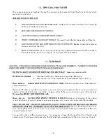
Initial  heating  of  oven  may  generate  smoke  or  fumes  and  must  be  done  in  a  well  ventilated  area. 
Overexposure to smoke or fumes may cause nausea or dizziness.  


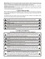
FOR YOUR  SAFETY:

  Do  not  store  or  use  gasoline  or  other  flammable  vapors  and 

liquids in the vicinity of this or any other appliance.

!

!


WARNING:

 Improper installation, adjustment, alteration, service or maintenance can 

cause  property  damage,  injury  or  death.  Read  the  Installation,  Operating  and 
Maintenance Instructions thoroughly before installing or servicing this equipment. 

!

!

COUNTERTOP MODEL            

GAS IMPINGEMENT CONVEYOR OVEN

BAKERS PRIDE OVEN CO., INC

.

30 Pine Street

New Rochelle, NY 10801

+1 (914) 576-0200  Phone                                                                         


(800) 431-2745   


US & Canada

+1 (914) 576-0605  Fax                                                                  


 www.bakerspride.com     Web Address

         [email protected]  


e-mail Address

1

   P/N U4174A  2/08

ANSI/NSF4

Summary of Contents for VH-1828G-1

Page 1: ...o smoke or fumes may cause nausea or dizziness FOR YOUR SAFETY Do not store or use gasoline or other flammable vapors and liquids in the vicinity of this or any other appliance WARNING Improper installation adjustment alteration service or maintenance can cause property damage injury or death Read the Installation Operating and Maintenance Instructions thoroughly before installing or servicing thi...

Page 2: ...ons 8 9 System Check 9 10 Initial Startup 10 11 Shutdown 11 12 Special Features 12 13 Cleaning 12 14 Operator Maintenance 14 15 Rating Plate 15 16 Conveyor Removal 15 17 Conveyor Installation 15 18 Conveyor Belt Speed Calibration 16 19 Troubleshooting Guide 18 20 Temperature Control Conversion Chart 22 21 Electrical Schematic Wiring Diagram 23 22 Parts Lists Exploded Views 25 23 Warranty 31 2 Note...

Page 3: ...e defined as follows CAUTION These models are designed built and sold for commercial use If these models are positioned so the general public can use the equipment make sure that cautions warnings and operating instructions are clearly posted near each unit so that anyone using the equipment will use it correctly and not injure themselves or harm the equipment WARNING Check the data plate on this ...

Page 4: ...iquefied petroleum gases when making gas connections WARNING The appliance must be isolated from the gas supply piping system by closing its manual shut off valve during any pressure testing of the gas supply piping system at test pressures equal to or less than 1 2 psig 3 45kpa WARNING The appliance and its shut off valve must be disconnected from the gas supply piping system during any pressure ...

Page 5: ... to obtain a qualified technician for the required maintenance service 5 CAUTION This product when stacked has more than one power supply connection point Disconnect all power supplies before servicing WARNING SHOCK HAZARD Do not open any panels that require the use of tools WARNING Neglecting to keep fan opening clean could result in control failure WARNING Failure to provide clearances will caus...

Page 6: ...iled in Section 1 above DO NOT LIFT EXCESSIVE WEIGHT A Legs are shipped unattached Make sure each leg is attached and tightened before placing the conveyor oven in place Each leg is adjustable to accommodate variations in the mounting surface B Using sufficient help 2 or more people lift the conveyor oven upward and place on the countertop surface Lift the conveyor oven by gripping the bottom of t...

Page 7: ...from upper unit When stacking align Dimpled Foot of upper unit into matching Dimple of bottom unit Use Stacking Brackets to secure ovens together 7 6 STACKING CAUTION Normal cooking operations may result in the production of smoke or fumes and may cause nausea and dizziness Be sure the oven is placed in a well ventilated area 7 ELECTRICAL CONNECTIONS General Instructions b Make sure the electrical...

Page 8: ...as 4 W C Propane Gas 10 W C C The installer must also supply a separate shut off valve between the gas supply and the appliance gas regulator D If a flexible gas supply line is used it must connected as shown in the diagram below The flexible connection must allow for movement without causing links in the hose A sufficient restraining device must also be attached to any portable mounting device to...

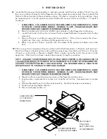
Page 9: ... from the front of the unit Direction of travel is controlled by a Reversing Switch that is located inside the control box containing the gearmotor If the direction of travel needs to be reversed follow this procedure 1 2 Reversing the conveyor belt requires opening the Power Control Box door 3 Locate a small rocker switch mounted just inside the control box Two wires are connected to it 4 Change ...

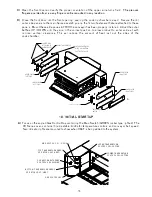
Page 10: ... heat lost out the sides of the cook chamber ADJUSTABLE BAFFLE LOWER COVER LEFT SIDE H NGER PINS ATTACHED TO UPPER COVER A UPPER COVER RIGHT SIDE LOWER COVER RIGHT SIDE UPPER COVER LEFT SIDE ADJUSTABLE BAFFLE 1 4 TURN FASTENERS 2 TOP 2 BOTTOM CAPTIVE TO COVER 10 10 INITIAL STARTUP A Focus on the angled Gas Control Box containing the Main Switch GREEN rocker type lighted The VH Series oven contains...

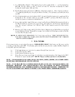
Page 11: ...at this process turning the knob Clockwise verifying that the conveyor belt moves slower AT SPEED SETTINGS ABOVE 10 10 minute cook time IT MAY BE HARD TO TELL THE BELT IS MOVING PLACE A PAN ON THE BELT TO OBSERVE THAT IT MOVES INTO THE COOK CHAMBER The conveyor oven is supplied with a special that helps cool the oven quickly once the unit has been shut OFF This feature performs the following funct...

Page 12: ...by using any commercial cleaner recommended for stainless steel Always rub with the grains and apply very light pressure Standard construction of the interior cook chamber is of aluminized steel and requires care not to over clean and scratch the surface Use only the detergent solutions and cleaners that meet national and or local codes Clean the walls of the cook chamber with a mild soap and wate...

Page 13: ...while cooking This 3 piece assembly comes apart for cleaning as shown below NOTE USE CARE IF CLEANING THE CONVEYOR BELT WHILE IT IS STILL MOUNTED IN THE OVEN EXCESSIVE FORCE MAY PRODUCE AN OVERLOAD CONDITION THAT COULD DAMAGE THE GEARMOTOR AND CAUSE THE OVEN TO BE RENDERED UN USABLE 13 Although symmetrical in design inner panel must have flanges facing up as shown Inner Perforated Screen Stainless...

Page 14: ...turn the knobs back and forth calling for heat It is very unlikely that the light will burn out 5 If there is no air blowing check the following A Observing the at the beginning of this section open the Power Control Box and locate the overload relay above gearmotor Try the Main Switch again 1 NOTE meaning that if one or both of the blower motors get jammed the overload relay shuts the motor s OFF...

Page 15: ...em upwards to clear the conveyor frame Flanges on the trays hook around the ends of the frame b Remove the two crumb pans c Remove the upper outer side covers which have the adjustable baffles attached with pins The covers are held in place with hand twist fasteners Turn these fasteners 90 counterclockwise to loosen and 90 clockwise to tighten d Remove the two vertical frame spreaders that support...

Page 16: ... mark the frame in the same manner C These distances represent exactly of the length of the cook chamber x 28 cook chamber 7 D With this 1 4 ratio it is possible to calibrate the belt speed For example 1 For a cook time of 1 minute the time required to pass between timing marks would be 60 seconds 4 15 seconds If the belt passes from one mark to the next in 15 seconds this is exactly the same as a...

Page 17: ...e method described H Cook Bake Time is not the same as time of delivery is the actual time required for the first item leading edge to trailing edge is leading edge to leading edge For example the for a 16 pizza with a 6 minute using the DualAir 1828 conveyor is 9 4 minutes NOTE Time of Delivery Cook Bake Time Time of Delivery Bake Cook Time 17 Bake Time Leading Edge of Product Time will be the sa...

Page 18: ... remove one belt link Tighten conveyor belt using adjustable tensioner at one end of belt frame Properly re attach and tighten to gearmotor output shaft Remove belt assembly to identify obstruction to belt movement Remedy problem Straighten bent belt links Tighten setscrew to gearmotor output shaft shaft is flatted for setscrew grip Align and engage shaft pin to slot in drive coupling Install mast...

Page 19: ...REACHING INTO BLOWER WHEEL COMPARTMENT SERIOUS INJURY COULD RESULT OTHERWISE THE PROBLEM THE CAUSE THE SOLUTION CAUTION THE FOLLOWING TESTS 1 5 ARE PERFORMED WITH LIVE POWER WITH CONTROL BOX OPEN OR REAR MOTOR COVER REMOVED THESE TESTS TO BE PERFORMED ONLY BY AN AUTHORIZED SERVICE AGENT No air or not enough air coming from blower s Continued Conveyor gearmotor failed Continued Turn Main Switch OFF...

Page 20: ... Oven not hot enough Continued Temperature control not working properly Continued 5 If both sensors are good swap sensor leads between controls Turn temperature knobs ON OFF Whichever light works properly the Replace OPPOSITE control is bad Burners not working properly THIS TYPE OF DIAGNOSTICS TESTING CAN ONLY BE PERFORMED BY AN AUTHORIZED SERVICE AGENT 4 If both burners are on run for 10 15 minut...

Page 21: ...ify each 3 wire burner harness is properly connected to 12 pole terminal block 7 At 12 pole terminal block verify all wires are tight by exerting small pull on each wire 8 If one burner lights determine which ignition module is operating properly and swap ignition harnesses between modules Check if burner ignition problem follows ignition module 9 To verify if gas valve is operating correctly swap...

Page 22: ...8 1370 1379 1391 1399 32 34 40 44 50 54 60 64 70 74 80 84 90 94 100 104 110 114 120 124 130 134 140 144 150 154 160 164 170 174 180 184 190 194 200 204 210 214 220 224 1411 1420 1432 1440 1452 1460 1473 1481 1493 1501 1513 1521 1533 1541 1554 1562 1574 1582 1594 1602 1614 1622 1634 1642 1654 1662 1674 1682 1694 1702 1714 1722 1734 1742 1753 1761 1773 1781 1793 1801 230 234 240 244 250 254 260 264 ...

Page 23: ...r BLUE YELLOW or BLUE ORANGE PURPLE ORANGE PURPLE LOWER UPPER LOWER BURNER ASSEMBLY 18 GA BLUE WHITE TO TERMINAL BLOCK 4 18 GA ORANGE 18 GA BLUE 32 58 BLACK ORANGE PURPLE BLUE BURNER FLAME SENSOR IGNITER BURNER FLAME SENSOR IGNITER 14 GA HI TEMP ITEMS LOCATED AT FRONT OF MAIN CHAMBER ASSEMBLY 14 GA HI TEMP 14 GA HI TEMP 18 GA WHITE 18 GA BLACK 18 GA GREEN TERMINAL BLOCK 4 VACUUM SWITCHES TUBES TO ...

Page 24: ...E IGNITER TRANSFORMER 120 VAC 24 VAC 10 AMP GAS INJECT G 4 5 2 1 3 11 10 9 8 7 6 L1 FLAME SENSE GROUND THERMOSTAT GAS VALVE IGNITER TRANSFORMER 120 VAC 24 VAC 10 AMP GAS INJECT G UPPER T EMPERAT URE CONTROL LOWER TEMPERATURE CONTROL VACUUM SWITCHES CLOSE ON RISING VACUUM ORANGE BLUE PURPLE RTDSENSOR ORANGE BLUE PURPLE RTDSENSOR GAS VALVE BURNER FLAME SENSOR IGNIT ER UPPER IGNITION MODULE GAS VALVE...

Page 25: ...for Item 1 REMOVABLE FRAME SPREADER OUTER UPPER COVER RIGHT RETAINING RING for Item 4 OUTER LOWER COVER RIGHT 1 4 TURN FASTENER HANGER PIN ADJUSTABLE BAFFLE 1 2 3 4 5 6 7 8 9 10 11 1 2 6 6 1 1 1 2 18 1 1 B6089U S3270A B6087U S3253A S3259A Q4045A S3267U B6068U S3254A B6345T S3266U INFEED EXTENSION TRAY METAL SPROCKET DISCHARGE EXTENSION TRAY COMPLETE WIRE BELT ASSEMBLY WIRE BELT MASTER LINK NOT SHO...

Page 26: ...V FAN GUARD FAN CORD ASSY REAR BLOWER MOTOR COVER RUBBER BUMPER COMPLETE REAR BLOWER MOTOR COVER ASSY ITEMS 2 6 1 2 3 4 5 6 1 2 1 2 1 2 B6027K M1510A B6031K S3260A M1548U M1548A MOTOR MOUNT BRACKET ASSY MAIN BLOWER WHEEL MOTOR MOUNT PLATE HEAT SLINGER WHEEL COMPLETE BLOWER MOTOR ASSY ITEMS 2 6 BLOWER MOTOR 1 4 HP 115 230 V 1 PH 1 2 3 4 1 1 1 1 M1385A M1386A B6086U P1150Z CONTACTOR 15A 3 POLE 115V ...

Page 27: ...4A CONTACTOR 15A 3 POLE 115V CONTACTOR MOUNT BRACKET ASSY OVERLOAD RELAY RATING PLATE MOTOR STARTER ASSY ITEMS 24 26 COOLING FAN FILTER GUARD 3 PIECE ASSY FILTER MEDIA PKG OF 5 TEMPERATURE CONTROL 115V 150 600 F COOLING FAN 115V HINGED DOOR ASSY ITEMS 17 22 HINGED DOOR ASSY BARE GEARMOTOR REVERSING SWITCH REVERSING SWITCH MOUNT BRACKET GEARMOTOR ADJUSTMENT PLATE GEARMOTOR ADAPTER PLATE GEARMOTOR C...

Page 28: ...24VAC TERMINAL BLOCK 12 POLE VACUUM SWITCH VACUUM SWITCH MOUNT BRACKET FILTER MEDIA PKG OF 5 COOLING FAN FILTER GUARD 3 PIECE ASSY COOLING FAN 115V COOLING FAN INNER GUARD METAL COOL DOWN RELAY 115V TERMINAL BLOCK 8 POLE U BOLT MANIFOLD CLAMP GAS MANIFOLD MOUNT BRACKET PIPE CLAMP HINGED DOOR ASSY ITEMS 21 26 HINGED DOOR ASSY BARE POTENTIOMETER AIR TEMPERATURE CONTROL POTENTIOMETER BELT CONVEYOR SP...

Page 29: ...N THERMOSTAT 2 1 2 3 6 7 8 9 1 2 3 4 5 6 7 8 9 1 1 1 1 1 1 1 1 1 B6318U L5106A N5876A R3224P R3245P N3084A M1167A B6318K M2140A BURNER ASSY 25K BTU HR ITEMS 2 9 GAS BURNER ASSY MINUS AIR SHUTTER ADJUSTABLE AIR SHUTTER ORIFICE HOOD 43 NATURAL GAS ORIFICE HOOD 53 PROPANE GAS BRASS ELBOW FITTING ORIFICE HOOD MOUNT FLAME SENSOR BURNER ASSY MOUNT BRACKET GAS IGNITER ELECTRODE 1 2 3 4 5 6 7 8 9 Entire A...

Page 30: ...2 1 1 R5877A R5878A UPPER GAS MANIFOLD TUBE LOWER GAS MANIFOLD TUBE Part Number Description Quan Figure L Gas Valve Assembly Item 1 2 3 4 2 2 2 2 R3225A R3227P N3068P R3226A GAS VALVE ASSEMBLY NATURAL GAS GAS VALVE ASSEMBLY PROPANE GAS PRESSURE NOZZLE CONVERSION KIT NAT GAS TO L P 1 2 3 4 1 2 3 4 30 ...

Page 31: ...THREE MONTHS The installation of these replacement decks is the responsibility of the purchaser The extended Cyclone door warranty years 3 through 5 is a parts only warranty and does not include labor travel milage or any other charges EXCLUSIONS Negligence or acts of God Thermostat calibrations after 30 days from equipment installation date Air and Gas adjustments Light bulbs Glass doors and door...

Page 32: ...AKERS PRIDE BAKERS PRIDE OVEN CO INC 30 Pine Street New Rochelle NY 10801 1 914 576 0200 Phone 800 431 2745 US Canada 1 914 576 0605 Fax www bakerspride com WebAddress info bakerspride com e mailAddress 32 ...

Reviews: