background image

Page 

27

 of 

55


Anaerobic Monitoring (Optional Extra)


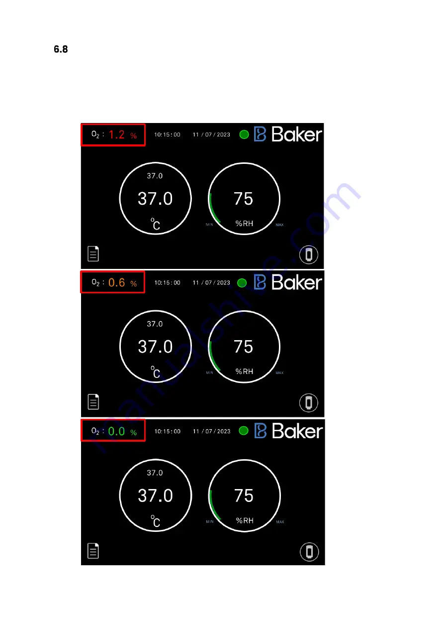
The Anaerobic Monitoring option displays the current level of Oxygen present within the 
workstation. The O2 display can be seen in the top left of the screen. The O2 level text changes 
colour based on the alarm set points that have been set. O2 alarm 2 is indicated by a red text. O2 
alarm 1 is indicated by an amber text. Anaerobic conditions are displayed by a green text.


Summary of Contents for Bugbox Ax

Page 1: ...Bugbox Ax User Manual UM 053 R1 0 1 Bugbox Ax Anaerobic Workstation UM 053 Affix Serial Number Sticker Here...

Page 2: ...5 C to 45 C o Accurate and automated humidity control no dry spots o Palladium catalyst maintains anaerobic environment plus anaerobic colour indicator strips verify anoxic conditions o Ezee Sleeve sy...

Page 3: ...tion 11 Environmental Operating Conditions 11 Service Requirements 12 Electrical Supply Requirements 12 Gas Supply Requirements 13 Workstation overview 14 Workstation layout 14 Component layout 14 Fro...

Page 4: ...ck outer door 32 Opening the interlock inner door 32 Transferring material into the workstation chamber via the interlock 33 Removing material from the workstation chamber via the interlock 33 Hand ac...

Page 5: ...sing the workstation The Baker Company Baker or Ruskinn Technology Ltd Ruskinn does not accept responsibility for accidents to personnel or damage to the Bugbox Ax workstation resulting from incorrect...

Page 6: ...Over pressure could damage the workstation Only the gases specified in this user manual may be used All gas bottles must be adequately secured before connection to the workstation The maximum power ra...

Page 7: ...EEE Directive This product must not be treated as household waste Instead it shall be handed over to an appropriate collection point for the recycling of electrical and electronic equipment If in doub...

Page 8: ...ence in which case the user will be required to correct the interference at his own expense Precautions The Bugbox Ax has been tested and approved to EN61010 1 61326 1 and 61326 2 6 This means that th...

Page 9: ...er to this manual in all cases where this symbol appears in order to find out the nature of the Potential Hazard and actions to be taken in order to avoid the Hazard Warning this equipment contains hi...

Page 10: ...m Workstation chamber internal width 540 mm Workstation chamber internal height 535 mm Workstation chamber internal depth 546 mm Interlock internal width 149 mm Interlock internal height 285 mm Interl...

Page 11: ...cal distributor The mains appliance coupler and plug are the AC mains supply isolation device and must be easily accessible For optimal performance the Bugbox Ax should not be installed directly benea...

Page 12: ...uency as stated on the rating label shown at the rear of the unit The mains supply voltage fluctuations must not exceed 10 of the nominal mains voltage The input voltage and frequency for Bugbox Ax wo...

Page 13: ...rial or medical 42 to 72 5psi 3 to 5 bar Table 4 Standard Gases For the gas supply we recommend direct connections of the gas bottle regulator to ensure minimal pressure drops and flow rate restrictio...

Page 14: ...by the glove ports and the interlock The interlock consists of the interlock chamber with an inner and an outer door The Bugbox Ax workstation is controlled via the control panel Component layout Ple...

Page 15: ...Page 15 of 55 Rear view Figure 4 shows the rear view of the Bugbox Ax workstation Figure 4 Bugbox Ax workstation rear view...

Page 16: ...orkstation left side view 1 Condenser fan Intake Do not obstruct 2 Condensate tank drain pipe 3 Universal Cable Gland optional extra 4 Single Plate Entry System optional extra 5 Glove Port Stowage Bra...

Page 17: ...Page 17 of 55 Right side view Shows the right side view of the Bugbox Ax workstation Figure 6 Bugbox Ax workstation right side view 1 Interlock Fan Intake Do not obstruct 1...

Page 18: ...orkstation Figure 7 Bugbox Ax workstation control panel 1 Temperature Set Point 2 Temperature Reading 3 ANO2 Low Alarm Icon 4 N2 Low Alarm Icon 5 Trend Log Button 6 Time Date Settings Button 7 Humidit...

Page 19: ...can be set using the temperature controller settings on the touchscreen Setting the temperature 1 Press the temperature controller dialog on the touchscreen 2 The Temperature Control Input Keypad wil...

Page 20: ...rge button This pre conditions the interlock atmosphere to not affect the internal workstation atmosphere To run an interlock purge first ensure that both the inner and outer door are closed Then pres...

Page 21: ...water that is then evaporated into the workstation atmosphere The workstation allows the humidity to rise to a user defined maximum at which point it will start to strip the excess humidity away at a...

Page 22: ...g Menu 2 Internal Light On Off Press to switch on or off internal light 3 Internal Socket On Off Option Press to switch the power to the internal socket on or off 4 Time Date Settings 5 Offsets 6 Alar...

Page 23: ...w pressure is detected 2 Forced Demand Press to toggle forced demand option on or off When forced demand is on a 2 second shot of Hydrogen will be injected every 20 minutes regardless of workstation l...

Page 24: ...Page 24 of 55 Time Date Settings Figure 11 Time Date Menu 1 Increase button Press to increase the value of the time date 2 Decrease button Press to decrease the value of the time date 1 2...

Page 25: ...main menu can be offset to match a preferred external sensor if required Press the value and enter the desired offset value 2 Humidity Sensor Offset The humidity reading on the main menu can be offset...

Page 26: ...te Time Temperature and Humidity readings logged every minute A Micro SD card must be installed for logging to take place The on screen log displays the values from the last 10 minutes recorded at 1 m...

Page 27: ...of Oxygen present within the workstation The O2 display can be seen in the top left of the screen The O2 level text changes colour based on the alarm set points that have been set O2 alarm 2 is indica...

Page 28: ...Page 28 of 55 To access the alarm set points press the O2 value The alarm set points can be changed by pressing the values shown below...

Page 29: ...c conditions monitor should be calibrated at least once a month and on installation To access the calibration menu press the settings O2 calibration icon and then press start When the O2 calibration h...

Page 30: ...Slot 1 Micro SD Card Slot To enable data logging insert the Micro SD card that was supplied with the workstation To remove the Micro SD card push gently on the it s edge to release Note Data logging w...

Page 31: ...ironment inside the workstation chamber using the anaerobic indicator strips Open the interlock outer door see section 8 1 2 Place the anaerobic indicator strips in the interlock Close the interlock o...

Page 32: ...icate that the door is closed Note Do not open the interlock outer door if the interlock inner door is open Do not place object s on the interlock outer door as this may damage the workstation Do not...

Page 33: ...8 2 for more details Open the interlock inner door see section 8 1 3 for more details Remove the Petri dish holder from the interlock Close the interlock inner door see section 8 1 3 for more details...

Page 34: ...is provided via the Ezeeyin glove ports and Ezee Sleeve The Ezee Sleeve consists of a gloveless gas tight sleeve and a cuff The Ezee Sleeve attaches to the glove port via two O rings Note The worksta...

Page 35: ...zee Sleeve before inserting the hand and arm as shown in Figure 16 Figure 16 Compressed Ezee Sleeve for Entry Hold the desired Ezee Sleeve cuff with the opposite hand Support the Ezee Cuff push the ha...

Page 36: ...ion should be continued until the maximum amount of external atmosphere has been removed from the Ezee Sleeve and the Ezee Sleeve exerts some pressure on the arm hand Figure 19 Ezee Sleeve before vacu...

Page 37: ...e Sleeve removal of the Cap can require a reasonable amount of force This can be made easier by pushing the uppermost part of the Handle to first break the vacuum at the upper edge of the Cap seal Fig...

Page 38: ...Page 38 of 55 Figure 22 Glove port cap storage location inside workstation Repeat the procedure for the other hand if both hands are entering the workstation chamber...

Page 39: ...the Glove Port replace the cap using the location posts and graphic to orient the Cap correctly on the Glove Port Note Care should be taken to ensure that the Ezee Sleeve material does not become caug...

Page 40: ...ptional extras Your Bugbox Ax workstation may be fitted with optional extra parts to provide added functionality The available optional extra parts for Bugbox Ax workstations are Single Plate Entry Sy...

Page 41: ...ob half a turn anti clockwise until the knob stops and lower the plate 2 Load plate through the opening 3 To close the SPES lift the flap into position and turn the knob a quarter of a turn to engage...

Page 42: ...station chamber The cable gland is suitable for cables of diameter 3 5mm to 7mm The cable gland port is located on the left hand side and is shown below Figure 26 Cable gland To use the cable gland Tu...

Page 43: ...ample port Replace the outer cap Figure 28 Gas Sample Port Vacuum port The vacuum port is used to remove liquids from the workstation chamber for example excess media from Petri dishes The vacuum port...

Page 44: ...vacuum hose from the vacuum port by pressing the top of the metal part of the internal section of the vacuum port and pulling the vacuum hose The hose should release from the vacuum port sealing the v...

Page 45: ...led water No other cleaning agents are permitted Cleaning agents should be applied to a clean paper towel and then to the workstation then removed using a clean paper towel Cleaning agents should not...

Page 46: ...er door o The glove port covers o If fitted the inside of the SPES For all workstation components wipe with a paper towel soaked in an appropriate cleaning agent Take care not to get cleaning agents o...

Page 47: ...nd the catalyst sachet need to be replaced annually See section 7 4 2 for ordering details It is recommended to replace both sachets at the same time Note Both sachets are replaced as part of an annua...

Page 48: ...approximately 1 hour Check that the environment in the workstation is anoxic using the anaerobic indicator strips If the environment in the workstation chamber is anaerobic samples cultures may be rei...

Page 49: ...t found Replace the mains fuses The fuse ratings are o 240V 50Hz F3 15A H250V o 220V 60Hz F3 15A H250V o 110V 60Hz F5A H250V o 100V 50 60Hz F5A H250V Fuses should be fast blow for example Cooper Bussm...

Page 50: ...rs Qualified service engineer To arrange an annual or biennial service contact your local distributor Note The biennial service includes an annual service Note The annual service includes the replacem...

Page 51: ...o Foamer Cleaning Tristel Fuse Sachet Cleaning Small Detox Sachet VOC filtration Small Catalyst Sachet Anaerobic operation Anaerobic Indicator Strips Anaerobic operation Accessories A range of accesso...

Page 52: ...tion temperature will not go above ambient plus 5o C The heater mat thermal protection switch has activated The heater mat fuse has blown Wait for the heater mat thermal protection switch to reset Con...

Page 53: ...cylinder High gas consumption when at rest The glove port cover has been left open The SPES has been left open The interlock inner and outer doors are both open Close the glove port cover Close the SP...

Page 54: ...ARTICULAR PURPOSE THE IMPLIED WARRANTY OF MERCHANTABILITY OR ANY IMPLIED WARRANTY ARISING OUT OF A COURSE OF DEALING OR OF PERFORMANCE CUSTOM OR USAGE OF TRADE Ruskinn Technology Limited DOES NOT WARR...

Page 55: ...s uk bakerco com Technical support support uk bakerco com General enquiries support uk bakerco com Website www bakerco com Ruskinn Technology Limited is a registered company in United Kingdom company...

Reviews: