AquaTrans™ AT600 User’s manual
19
Chapter 3. Wiring the AT600 electronics
Chapter 3. Wiring the AT600 electronics
3.1
Wiring diagram
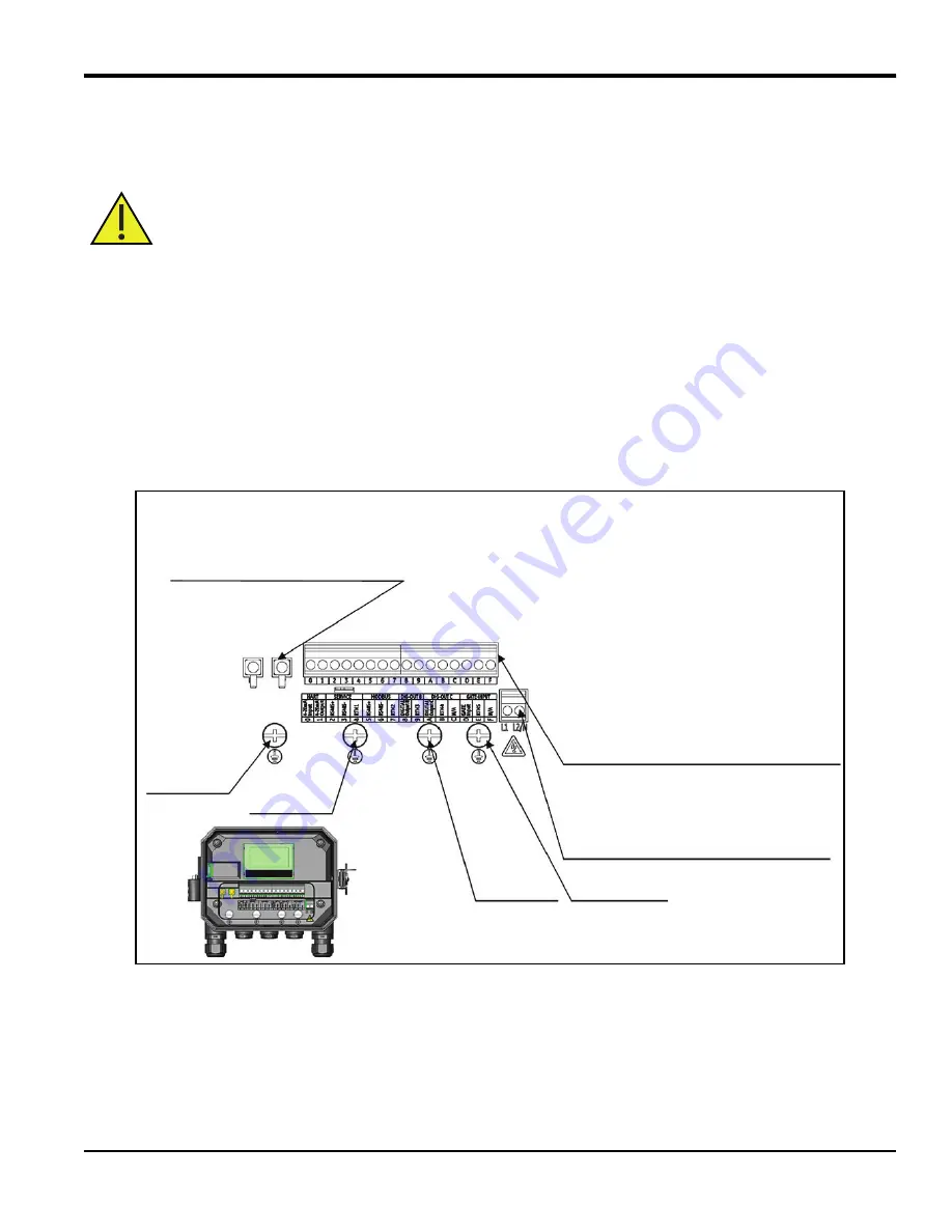
This section includes instructions for making all the necessary electrical connections to the AT600 flow meter. Refer to
figure 23 below for the complete wiring diagram of the meter.
IMPORTANT:
Except for the transducer connector, all electrical connectors are stored in their terminal blocks during
shipment and may be removed from the enclosure for more convenient wiring. Feed the cables through
the cable gland holes on the bottom of the enclosure, attach the wires to the appropriate connectors
and plug the connectors back into their terminal blocks.
After the AT600 is completely wired, proceed to "Initial setup and programming" on page 27 to configure the meter for
operation.
Note:
The HART and Modbus communication options must be selected when ordering the AT600.
Figure 23: Wiring diagram
Attention European Customers! To meet CE Mark requirements, all cables must be installed as
described in “Wiring cable specifications and requirements” on page 144.
GROUNDING 4
GROUNDING 3
GROUNDING 2
GROUNDING 1
DETAIL A
Input/output terminals
Label Description
0
Analog output A: 4-20mA/HART positive
1
Analog output A: 4-20mA/HART negative
2
Service Modbus port positive
3
Service Modbus port negative
4
Service Modbus port return ground
5
Customer Modbus port positive
6
Customer Modbus port negative
7
Customer Modbus port return ground
8
Digital output B port positive
9
Digital output B port negative
A
Digital output C port positive
B
Digital output C port negative
C N/A
D
Gate input port positive
E
Gate input port negative
F N/A
Note: Analog outputs are Namur NE43 compliant.
Power Terminals
PIN Label
Description
1
L1(+)
L(+): AC live power/DC positive
2
L2.NC(-)
N(-): AC neutral/DC negative
Transducer terminals
PIN Label
Description
1 DN
Downstream
transducer
2 UP
Upstream
transducer
Summary of Contents for Panametrics AquaTrans AT600
Page 1: ...panametrics com BH001C11 Rev F AquaTrans AT600 User s manual...
Page 2: ......
Page 4: ...ii no content intended for this page...
Page 10: ...Contents viii AquaTrans AT600 User s manual no content intended for this page...
Page 150: ...Chapter 6 Communication 140 AquaTrans AT600 User s manual no content intended for this page...
Page 158: ...Appendix B Specifications 148 AquaTrans AT600 User s Manual no content intended for this page...
Page 162: ...Appendix C Specifications 152 AquaTrans AT600 User s Manual no content intended for this page...
Page 172: ...Warranty 162 AquaTrans AT600 User s Manual...
Page 173: ......


