


Note:
The LCD backlight flashes to signal errors. If the
backlight is Off when an error is detected, the display is
illuminated briefly, but if the backlight is already On, the
light is interrupted briefly. In addition, Error Code messages
may appear in the upper right corner of the LCD display.
4.4 The optional PanaView display
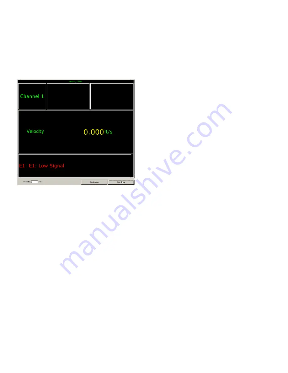
The components of the PanaView text display are shown in
Figure 18
below, along with a typical flow rate readout.
Figure 18: A Typical PanaView text display pane
As shown in
Figure 18
above, the
PanaView
text pane
includes the following information:
• Channel Number
• Flow Parameter
• Units of Measure
• Flow Rate Value
However, the items in this list may be reprogrammed to
display a variety of alternative choices (see
“Programming
the PanaView Display” on page 40
).
Note:
As shown in Figure 18 above, Error Code messages
may appear in the lower left corner of the PanaView text
display window.
4.5 Taking measurements
The
PanaFlow Z1G/Z2G Process Gas Flowmeter
is capable
of displaying several different variables in a variety of
formats. However, this manual discusses only the basic
measurement displays using the LCD display or the
PanaView display. Refer to the PanaView User’s Manual
(Panametrics document #910-211) for details on using
PanaView and the
PanaFlow Z1G/Z2G Process Gas Flowmeter
analog outputs to obtain the flow rate data.
4.5.1 Programming the LCD display
Note:
When you first initialize the PanaFlow Z1G/Z2G Process
Gas Flowmeter, the number of LCD parameters is set to
OFF. You must program the LCD to display any measured
parameters.
Using the
Keypad Program
, you can program the LCD display
to display up to four variables in sequence. Complete the
following steps to program the LCD display:
1. Power up the
PanaFlow Z1G/Z2G Process Gas Flowmeter
and wait until it has initialized.
2. To enter the
Keypad Program
, press the [
] key, followed
by the [
] key, and the [
] key again. Each successive
key must be entered within 10 seconds of the prior key.
3. In the
Keypad Program
window, scroll to
PROG
and press
[
].
4. In the
PROG
menu, scroll to
GLOBL
and press [
].
5. Scroll to
I/O
and press [
].
6. Scroll to
LCD
and press [
].
7. At the
# of LCD Parameters
screen, scroll to the
desired number (from
OFF
through
1-4
and
KEY
) and
press [
]. The
OFF
setting switches the measurement
display Off. The
KEY
setting enables users to change
the measurement display with the arrow keys, without
accessing the
Keypad Program
. If you select
KEY
:
• To view a parameter other than the one currently
displayed, press the [
] and [
] keys to scroll through
the various available parameters.
8. Select the desired
Measurement Parameter
(see
Table 8
on page 38
for a list of the available parameters).
24
Summary of Contents for PanaFlow Z1G
Page 1: ...PanaFlow Z1G Z2G User s manual 910 321 Rev A...
Page 2: ...ii...
Page 4: ...no content intended for this page iv...
Page 9: ...no content intended for this page 1...
Page 21: ...Figure 12 Remote mount electronics transducer and preamplifier wiring ref dwg 702 731 732 13...
Page 28: ...no content intended for this page 20...
Page 30: ...no content intended for this page 22...
Page 38: ...no content intended for this page 30...
Page 40: ...no content intended for this page 32...
Page 43: ...Table 13 Service record cont Date Description of service Performed by 35...


