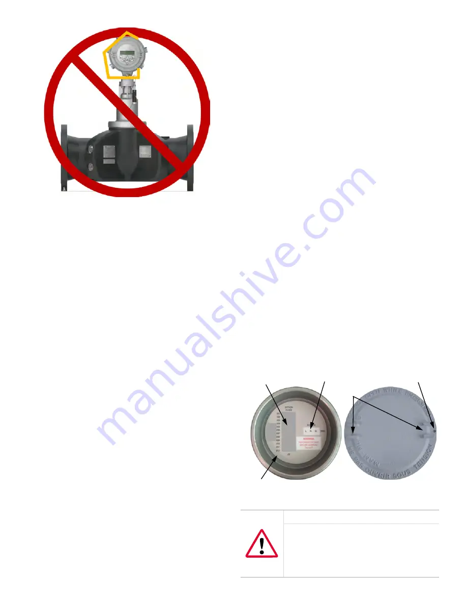
Figure 8: Improper lifting method
2.3 Flowcell location guidelines
The flowcell includes the flow transducers and, optionally,
pressure and temperature transmitters. Ideally, install the
flowcell in a section of pipe with access to the flowcell, such
as a long run of pipe that is above ground. Observe the
following recommendations:
• There should be at least 20 pipe diameters of straight,
undisturbed flow upstream and 10 pipe diameters
of straight, undisturbed flow downstream from the
measurement point. To ensure undisturbed flow, avoid
sources of disturbances in the fluid such as valves,
flanges, expansions, and elbows.
• Because condensate or sediment at the bottom of the
pipe may cause attenuation of the ultrasonic signal,
always install the
PanaFlow Z1G/Z2G Process Gas
Flowmeter
with the transmitter in a vertical orientation
on the top of the pipe. This ensures that the transducers
are located on the sides of the pipe rather than on the
top or bottom.
• Only authorized personnel should perform the
installation. The proper personal protection equipment
(PPE) should always be used when working with this
equipment.
• The flowcell shall be installed in such a way that it can
be safely operated, maintained and inspected. Please
refer to specific outline and installation drawings for
proper clearances and specific distances for each
system size. In general, allow for a minimum of 12” of
space on all sides of the flowcell and flow transmitter,
with an ideal clearance of 24” on all sides.
• You must provide suitable over-pressure protection
at the main piping to the flowcell in order to prevent
damage to the flowcell and injury to personnel. The
utilized over-pressure protection device shall be
supplied with all declarations of conformity and EC-type
design certificates.
• Make sure the difference between the inside diameter of
the pipe and that of the
PanaFlow Z1G/Z2G Process Gas
Flowmeter
does not exceed 0.5%, as changes in internal
diameters will cause flow profile disturbances.
• Make sure any non-symmetrical offset does not exceed
1%, as misalignment between the piping and the meter
may cause flow profile disturbances.
• Make sure the gasket is centered on the flange faces
and does not protrude into the pipe, as protrusion
of the gasket into the pipe may cause flow profile
disturbances.
• If pipe insulation is required, install all insulation
materials and accessories in accordance with the
manufacturer’s instructions and recognized industry
practices. Adhere to the local code where applicable to
ensure that the safe and proper installation will serve its
intended purpose.
2.4 Making the electrical
connections
This section contains instructions for making all the
necessary electrical connections to the
PanaFlow Z1G/Z2G
Process Gas Flowmeter
. Refer to
Figure 13
on page 14 for a
complete wiring diagram.
Note:
Except for the power connector, all electrical
connectors are stored on their terminal blocks during
shipment and may be removed from the enclosure for
more convenient wiring. Simply, feed the cables through the
conduit holes on the side of the enclosure, attach the wires
to the appropriate connectors, and plug the connectors
back into their terminal blocks.
To prepare the
PanaFlow Z1G/Z2G Process Gas Flowmeter
for
wiring, refer to Figure 9 below, and complete the following
steps:
Inside View
Wiring Label
Outside View
Option Card Connections
Power Connections
Set Screw
Slots
Figure 9: Rear cover with connection labels
WARNING!
Always disconnect the line power from the
PanaFlow Z1G/Z2G Process Gas Flowmeter
electronics before removing either the front
or rear cover. This is especially important in a
hazardous environment.
7
Summary of Contents for PanaFlow Z1G
Page 1: ...PanaFlow Z1G Z2G User s manual 910 321 Rev A...
Page 2: ...ii...
Page 4: ...no content intended for this page iv...
Page 9: ...no content intended for this page 1...
Page 21: ...Figure 12 Remote mount electronics transducer and preamplifier wiring ref dwg 702 731 732 13...
Page 28: ...no content intended for this page 20...
Page 30: ...no content intended for this page 22...
Page 38: ...no content intended for this page 30...
Page 40: ...no content intended for this page 32...
Page 43: ...Table 13 Service record cont Date Description of service Performed by 35...


