C. Lapping Nozzle Seats (Metal Seat,
Non-O-Ring Styles)
ATTENTION!
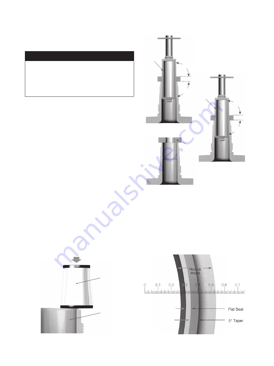
Nozzle laps as illustrated in Figure 35 are
available from Baker Hughes. Do not use
these laps if the valve nozzle can be removed
and machined to the seat dimensions
described in Table 3 and Table 4.
Lap the 5º angle of the nozzle first (Figure 35, View
A). Then, invert the nozzle lap and use the flat
side as a “starter” lap to ensure the seat is square
(Figure 35, View B). Use a ring lap in a circular
motion to finish lapping (See Figure 35, View C and
Reconditioning of Laps). Keep the lap squarely on
the flat surface and avoid rocking the lap, which will
cause roundingof the seat.
D. Lapped Nozzle Seat Widths
A wide nozzle seat will induce leakage, especially
in the smaller-orifice, lower-pressure valves. For
this reason, the seat of valves other than O-Ring
valves should be as narrow as practical. Since the
seat must be wide enough to carry the bearing load
imposed upon it by the pressure force, the higher
pressure valves must have wider seats than the
lower pressure valves. The nozzle seat width should
conform to the measurements in Table 3 and Table
4.To measure the seat width, use a Model S1-34-
35-37 Bausch and Lomb Optical Co. measuring
magnifier or an equivalent seven-power glass with
a 3/4” (19.05 mm) scale showing graduations of
0.005” (0.13 mm). Figure 36a and 36b illustrate the
use of this tool in measuring the nozzle seat width.
If additional lighting is required for measuring, use
a gooseneck flashlight similar to the Type A Lamp
Assembly (Standard Molding Corp.), or equivalent.
XIV. Maintenance Instructions (Cont.)
Nozzle Lap
90˚
85˚
Ring Lap
View A
View C
View B
Nozzle Lap
85˚
90˚
Figure 35: Lapping Nozzle Seats
Figure 36: Measuring Magnifier
Figure 36a: Measuring Magnifier
Measuring
Magnifier
Nozzle
Figure 36b: Magnifier Details
42 |
Baker Hughes
© 2021 Baker Hughes Company. All rights reserved.


