25
25
DIGITAL READOUT
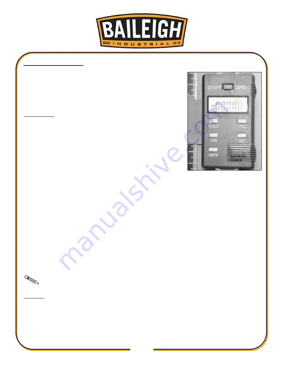
The digital scale equipped with
20” planer can serve many
applications, however for wood planning we need only concern
ourselves with the ON/OFF, SET, and mm/in buttons. When set
properly the digital readout will display the thickness of the
finished product.
Calibration:
In order to calibrate the unit first run a board through the planer
and measure the finished thickness with a set of vernier calipers.
This is the number to be entered into the display unit. At this
point turn the unit on by pushing the ON/OFF button. Now press
the mm/in button to set the unit to American standard or the
metric system.
1.
Press and hold the SET button until the ‘+’ sign starts to flash
and immediately release it.
2.
Cycle the set button by pressing it until the ‘+’ sign remains on.
3. Press and hold the SET
button until the second zero to the right of the ‘+’ plus sign starts to
flash and immediately release it.
4. Cycle the SET button by pressing it until the number reads the correct whole number taken
with the vernier calipers and immediately release the button.
5. Press and hold the SET button until the zero to the right of the decimal point starts to flash.
6. Repeat steps 4 and 5 until the last digit in the 0.001 place is entered.
7. Press and hold the SET button until the SET on the display starts to flashand immediately
release it.
8. Press and release the SET button one final time to complete the calibration.
Note:
Do not turn the device off. If you do you will have to re-calibrate the unit.
Battery:
When the display begins to flash the battery should be replaced. The battery is to be replaced
with a SR144 (or equivalent) and can be found at most pharmacies or grocery stores. When
replacing the battery the positive side of the button cell must face out.
Fig. 28
Summary of Contents for IP-208
Page 17: ...15 15 ELECTRICAL DIAGRAM...
Page 32: ...30 30 PARTS DIAGRAM SHEET 1 To Parts Sheet 2...
Page 33: ...31 31 PARTS DIAGRAM SHEET 2 To Parts Sheet 1...
Page 34: ...32 32 PARTS DIAGRAM SHEET 3...
Page 35: ...33 33 PARTS DIAGRAM SHEET 4...
Page 43: ...41 41 NOTES...


