


23
23
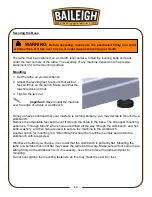
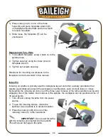
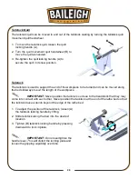
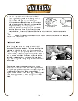
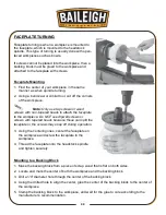
3. Place index pin (C) in one of the three
holes (D) and place faceplate wrench (E)
on faceplate shoulder flats and turn wrench
to loosen faceplate.
4. Once loose, the faceplate (F) can be
unscrewed.
Replacement Face Plate
1. To re-attach faceplate, screw it back on to the
spindle nose.
2. Tighten securely using the index pin and
faceplate wrench.
3. Tighten set screws securely.
Directions for mounting a workpiece to the
faceplate can be found later in this manual.
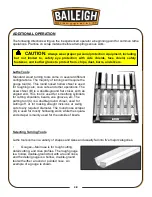
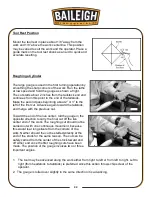
Index Pin
Indexing on a lathe is typically used for workpiece layout and other auxiliary operations that
require equal distances around the workpiece circumference, such as clock faces or inlays.
By inserting the indexing pin into one of the three outer indexes of the lathe spindle housing and
engaging one of the twelve inner indexes in the spindle, the workpiece can be positioned one of
36 equal points.
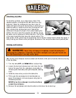
1. Turn off and unplug the lathe from the power
source.
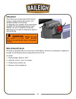
2. To use the indexing feature, rotate the
flywheel (A) so spindle is in desired location.
3. Place the index pin (B) into one of the
indexing holes (C) in the headstock.
IMPORTANT: Do not start the lathe
with the indexing pin inserted into the spindle.
This will cause damage to the lathe.
C
D
E
F
A
C
B
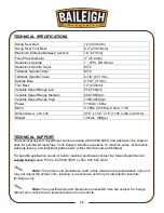
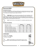
Summary of Contents for WL-1218VS
Page 41: ...38 38 WIRING DIAGRAM ...
Page 42: ...39 39 LATHE PARTS DIAGRAM ...
Page 49: ...46 46 NOTES ...
Page 50: ...47 47 NOTES ...
Page 51: ...48 48 NOTES ...