background image

Made in China |  INS-9205413-A-POWERPORT-ENG 2-3-2022

MANUFACTURED BY:
Backyard Discovery

3305 Airport Drive

Pittsburg, KS 66762

800-856-4445

PowerPort™

Model # 9205413

Wood Post Mounting Instructions

2 3/8 in [60 mm]

20

 1/8 in [51

2 m

m

]

966


(x4)

SCREW - 1 1/2"

413


(x1)

ELECTRICAL

ENCLOSURE

SCREW RAISED HEAD

8x1 1/2

(x4)

H100966

ELECTRICAL ENCLOSURE

(x1)

9205413

ENSURE THAT CORD END IS NOT

WITH-IN 6"- (152mm) OF THE GROUND

WHEN MOUNTING.

2 3/8 in [60mm]

20 1/8 in [512mm]

PRE-DRILL 1/8 IN - (3mm) PILOT HOLES

USING THE DIMENSIONS PROVIDED.

POST

Summary of Contents for FAIRHAVEN 2101524

Page 1: ...eda helpinghand Let our team of professionals handle the installation for you BILL GOCONFIGURE it OURS 888 888 5424 DOWNLOAD THE FREE APP T assembly time may vary based on skill level OglePlay Installation services are only available to U S customers o Store For the most up to date assembly manual to register your set or to order replacement parts please visit www backyarddiscovery com SAVE THIS A...

Page 2: ... indoor and outdoor recreation products that most consumers don t have the time or ability to deliver install themselves We do the heavy lifting so you don t have to 18 Years of Experience Servicing Big Box Retailers and Direct Consumers Satisfaction Guarantee Highly Skilled Specialized Courteous Professional Service Technicians Flexible Appointments including weekends Over 140 000 Installations A...

Page 3: ...e parts list from the manual that was included in your box Read entire assembly manual paying special attention to the important tips and safety information Ensure there are no missing pieces by first separating and identifying all parts Make sure to check packing material for small parts that may have fallen out during shipment Structures are not intended for public use Any unintended use such as...

Page 4: ...ng properties ofwood that do not affect performance or integrity Installation the warranty is null and void ifinstallation is not in accordance with the Assembly Instructions Labor for any inspection Labor for replacement ofany defective item s Incidental or consequential damages Cosmetic defects including rusting color fading minor cracks corrosion which do not affect performance or integrity ofa...

Page 5: ...ect wood parts monthly The grain of the wood inspection departments for guidance on applicable sometimes will lift in the dry season causing splinters to building codes and or zoning requirements appear Light sanding may be necessary to maintain a Wood is NOT ame retardant and will burn Grills re pits safe environment Treating your Product with protection and chimineas are a re hazard if place too...

Page 6: ...CK WASHER Bolt and Barrel Nut Assembly BOLT Insert barrel nut through the lock washer and press the pair through the provided hole Insert your bolt through the BARREL NUT second lock washer and insert the pair into the provided hole o LOCK WASHER opposite from the barrel nut Turn clockwise to thread into the barrel nut Do not completely tighten until instructed LOCK WASHER Lag Assembly LAG SCREW N...

Page 7: ...L SCREW T NUT WASHER FLAT BOLT HEX BOLT SCREW PWH H100545 H100695 H100699 H100706 H100716 H100718 H100742 7 _ _ I 1 i To help with assembly we recommend sorting your hardware bags with the seven digit alpha numeric number printed on the bags or by hardware type i e bolts nuts etc Organizing your hardware will make assembly easier Hardware Identification Hardware bags are printed with a seven digit...

Page 8: ... r 4 100 When you see this icon you will need a socket wrench The icons below show your bolts the size of attachments needed for 40 assembly 1 2 24 For proper assembly you will need to ensure that your structure is level before proceeding to the next step This icon warns you to not over tighten your bolts This is to prevent structural damage and also splintering your Some steps in the assembly pro...

Page 9: ... provided with your structure which allows you to permanently install your structure to a pre existing or new wood or concrete surface The hardware to attach the post mounts to the structure is included The hardware to mount the structure permanently to a concrete surface is included The hardware to mount the structure permanently to a wood deck is NOT included and will need to be purchased separa...

Page 10: ... 1 2 32x126x1002 D3I SLOTTED JOIST W4L14052 x8 1 1 4 x5 x114 32x126x2896 D4I JOIST W4L14053 x2 1 1 4 x5 x118 32x126x2998 05I JOIST W4L14054 x2 1 1 4 x5 x118 32x126x2998 D6I JOIST END W4L14081 x2 1 1 4 x5 x39 1 2 32x126x1002 07I JOIST END W4L14080 x2 1 1 4 x5 x39 1 2 32x126x1002 08ILONG ANGLE BRACE W4L14056 x8 1 1 4 x5 x36 1 4 32x126x922 10 ...

Page 11: ...x2 1 1 4 x5 x39 1 2 32x126x1002 D11IJOIST W4L14077 x2 1 1 4 x5 x71 3 4 32x126x1822 1 1 V1 IPURLIN W4L14078 x12 1 1 4 x1 1 4 x59 1 4 32x32x1507 V2IPURLIN W4L14079 x12 1 1 4 x1 1 4 x76 3 8 32x32x1942 II I s 1 I I I I WP1IPERGOLA POST W2A03070 x2 4 7 8 x4 7 8 x89 1 2 125x125x2273 II it I II II wp2 PERGOLA POST W2A03071 x2 I 4 7 8 x4 7 8 x89 1 2 125x125x2273 11 ...

Page 12: ... I 5 16x1 1 2 x50 I 5 16x7 8 0 H1002041LAG SCREW WH BLK x18 5 16x5 1 2 H100198I WASHER LOCK EXT BLK 4 111 1MMEIMIRMIM I x76 I 8x19 H100792I LAG SCREW WH BLK f ilMil 0 x13 I 1 4x3 H100854I LAG SCREW WH BLK H100199I WASHER LOCK EXT BLK x18 I 5 16x1 x60 I 12x19 Oill w H100877I SCREW TFH BLK 0 x100 8x2 1 2 H100405 I WASHER LOCK EXT BLK x13 I 6x15 IIIIII MP H100200ISCREW PFH BLK x17 8x1 1 2 11111111111...

Page 13: ...TORX BIT H100147I TORX BIT A100042I TORX BIT x2 T 20 x2 T 30 x2 T 40 H100114I TORX WRENCH x2 T 30 A100041I TORX WRENCH x2 T 40 II I _ I E _ N cdiv I NGSLEY PARK A4M x 0 8 1 157I POST BRACKET A1003141 A REVISION TAG A4M01163I xi KINGSLEY PARK TAG xi 41 1 1110 I A4M x 0 8 1 156I POST ANCHOR BRACKET A6I3 4 436 5x5 POST FOOT 13 ...

Page 14: ... I SCREW PFH BLK A6P00436I 5x5 POST FOOT x16 8x1 1 2 WP2I PERGOLA POST W2A03071 x4 x2 I 4 7 8 x4 7 8 x89 1 2 125x125x2273 c I COMPLETE THIS STEP TWICE TIP FOR EASE OF ASSEMBLY WE RECOMMEND USING SAW HORSEs FOR STEPS 1 THROUGH 4 WP1 xo PERGOLA POST WP2 0 PERGOLA POST 0 0 200 x8 SCREW 1 1 2 436 x2 5x5 POST FOOT 14 ...

Page 15: ...00192I NUT BARREL WH BLK H100792 I 1 4x3 LAG SCREW WH BLK x8 I 5 16x7 8 H100199I WASHER LOCK EXT BLK x4 x16 12x19 D9 xv WP2 xv Eniv C Iii SHORT ANGLE BRACE PERGOLA POST D9 xv SHORT ANGLE BRACE 7 D4 x 1JOIST to v I II 1 WP1 xt i i __ _ PERGOLA POST 3 D5 xi t JOIST 457 x2 354 x2 _ _I I BOLT 6 1 2 BOLT 2 198 x2 198 x2 WASHER 8x19 WASHER 8x19 I 405 O WASHER 6x15 A I 792 xi NOTES I I LAG SCREW 3 1 REPE...

Page 16: ...1001921NUT BARREL WH BLK H1001981WASHER LOCK EXT BLK H1001991WASHER LOCK EXT BLK x16 15 16x2 x16 I 5 16x7 8 x16 I 8x19 x16 I 12x19 NOTES REPEAT STEP TO COMPLETE TWO I INNER JOIST ASSEMBLIES D10 xi JOIST END D11 xi _______r______ 2 JOIST D2 xi i JOIST END T T lit 1 1 _ __ Sri D8 xt LONG ANGLE BRACE i 457 x4 D8 xt BOLT 2 LONG ANGLE BRACE T r 198 x4 WASHER 8x19 I as A _ Li NOTE OVERLAP AND 1 __ _ F B...

Page 17: ... H100192 1NUT BARREL WH BLK H1001981WASHER LOCK EXT BLK H1001991WASHER LOCK EXT BLK x16 I 5 16x2 x16 5 16x7 8 x16 I 8x19 x16 I 12x19 A NOTES REPEAT STEP TO COMPLETE TWO D7 x7 OUTER JOIST ASSEMBLIES JOIST END 77 tt i D1 xi D8 xi _ JOIST LONG ANGLE BRACE k k 457 x4 D6 xi vb I vv BOLT 2 JOIST END 198 X4 WASHER 8x19 D8 x7 t 4 LONG ANGLE BRACE NOTE PILOT HOLES I NOTE OVERLAP AND ON TOP OF JOIST p 1 1 B...

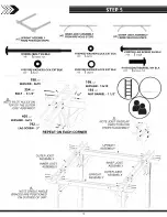
Page 18: ...199IWASHER LOCK EXT BLK H100193 NUT BARREL WH BLK I 5 16x1 1 2 x8 I 8x19 x8 I 12x19 x8 198 x2 WASHER 8x19 199 x2 Cr s WASHER 12x19 354 x2 193 x2 BOLT 6 1 2 NUT BARREL 1 1 2 I I kI m NOTE PILOTHOLES ON O f I TOP OF THE OUTER 1 1 JOIST ASSEMBLY 0 405 x2 WASHER 6x15 NOTE JOIST OVERLAP N 792 x2 DIRECTIONFOR A_ _ N LAG SCREW 3 PROPER ASSEMBLY i REPEAT ON EACH CORNER z V of 0 UPRIGHT ASSEMBLY I OUTER JO...

Page 19: ...H o 1 1 0 6 0 1981W 8xA 19 SHER LOCK EXT BLK x16 5 16x5 1 2 A NOTES LOCATE AND USE PILOT HOLES IN THE OUTER JOIST TO MOUNT D3 REPEAT ON OPPOSITE END AND ON ALL JOIST BOARDS AS SHOWN 204 x7 LAG SCREW 5 1 2 198 WASHER 8 19 1 o 1 I _ 1446 Tii I 1 JOIST I 4 H _ 0 8 SLOTTED JOI D 3 rii4ir if r ____ 1 lli bil 19 ...

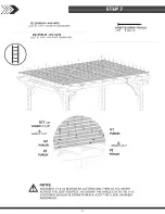
Page 20: ...x1 1 4 x76 3 8 32x32x1942 1 i I 9 IIIIIII0011 1 4r mon 11 877 x96 SCREW 1 1 2 _ V1 ANGLE CUT PURLIN V2 PURLIN ANGLE CUT V1 V2 PURLIN PURLIN NOTES A ASSEMBLE V1 V2 BOARDS BY ALTERNATING THEM AS YOU WORK ACROSS THE JOIST BOARDS AS SHOWN THE ANGLE CUT IN THE V1 V2 BOARDS SHOULD ALTERNATE WHICH JOIST THEY LAND ON WHEN ASSEMBLED 20 ...

Page 21: ... A4M01156I POST ANCHOR BRACKET x8 II IIIIIM H100480I BOLT WH BLK x8 5 16x4 3 4 i 6 i _ I ilik 1 IIV 6 ffi Al f z N _ z 471 x16 480 x8 1 LAG SCREW 1 BOLT 4 3 4 7 N I 192 x8 NUT BARREL 7 8 I a 1 11 _ v NOTE ABOVE THAT BOLT AND BARREL NUT ARE USED ON ANCHOR BRACKETS AND LAG 156 x8 157 x8 SCREWS ON PLAIN POST BRACKETS POST ANCHOR BRACKET POST BRACKET 21 ...

Page 22: ... IMMIMMIM3 A1003141 A REVISION TAG H100392 SCREW PWH BLK x1 x6 I 8x3 4 A4M01163I KINGSLEY PARK TAG x1 i i FRONT i x1 2 163 x KINGSLEY PARK TAG 1 illii ____ _ _ 392 04 _ SCREW 3 4 REAR iik I 314 O I 1 f 0 A REVISION TAG _ 392 0 2 SCREW 3 4 i 22 ...

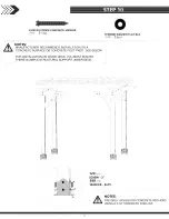
Page 23: ...T BLK x16 8x19 NOTES A MANUFACTURER RECOMMENDS INSTALLATION ON A CONCRETE SURFACE OR CONCRETE POST PADS SEE BELOW FOR INSTALLATION ON WOOD DECK YOU MUST ENSURE THERE IS AMPLE STRUCTURAL SUPPORT UNDER DECK I IF _ILL z 120 x16 SCREW 2 630 x16 n WASHER 8x19 I 1 NOTES A PRE DRILL HOLES FOR CONCRETE ANCHORS USING A 3 16 CONCRETE DRILL BIT 23 ...

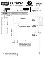
Page 24: ...205413 Wood Post Mounting Instructions 2 3 8 in 60 mm 20 1 8 in 512 mm 966 x4 SCREW 1 1 2 413 x1 ELECTRICAL ENCLOSURE SCREW RAISED HEAD 8x1 1 2 x4 H100966 ELECTRICAL ENCLOSURE x1 9205413 ENSURE THAT CORD END IS NOT WITH IN 6 152mm OF THE GROUND WHEN MOUNTING 2 3 8 in 60mm 20 1 8 in 512mm PRE DRILL 1 8 IN 3mm PILOT HOLES USING THE DIMENSIONS PROVIDED POST ...

Page 25: ...ckyard Discovery 3305 Airport Drive Pittsburg KS 66762 800 856 4445 SCREW TAPPING 10x1 1 4 x4 H100746 ELECTRICAL ENCLOSURE x1 9205413 MOUNTING BRACKET x2 A4M01292 PowerPort Model 9205413 Metal Post Mounting Instructions ...

Page 26: ...t to part 15 of the FCC Rules These limits are designed to provide reasonable protection against harmful interference in a residential installation This equipment generates uses and can radiate radio frequency energy and if not installed and used in accordance with the instructions may cause harmful interference to radio communications However there is no guarantee that interference will not occur...

Reviews: