RIGGING, INSTALLATION, OPERATION & MAINTENANCE MANUAL
TrilliumSeries
™
Adiabatic Products
–
Page 1: ...RIGGING INSTALLATION OPERATION MAINTENANCE MANUAL TrilliumSeries Adiabatic Products...
Page 2: ...ontrols are set up to periodically flush and drain the water system thereby eliminating the need for water treatment However there may be unusual circumstances where chemicals or biological contaminan...
Page 3: ...3 Piping Guidelines 13 Water Connection 16 Ammonia Installation Instructions 16 Customer Electrical Connections 17 Wiring and Electrical Information 23 Controls Setup for Microchannel Coils PART 4 Uni...
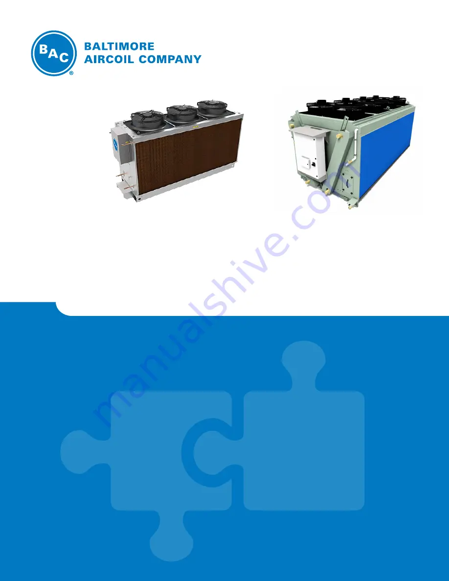
Page 4: ...TIC PRODUCTS Unit Description 1 Figure 1a TrilliumSeries Adiabatic Condenser TSDC Shown 4 7 2 1 1 2 3 3 4 Detail A TSDC Shown 13 8 9 10 11 17 13 14 Detail B TSDC2 Shown Figure 1b TrilliumSeries Adiaba...
Page 5: ...omatically closes 10 Sump This stainless steel basin collects the water from the gutters and the spray system and houses the pump s It can be accessed through the access hatch es 11 Strainer s The str...
Page 6: ...coil maintained pressure 15 psi by measuring the pressure with a Shrader valve prior to installation Fan Motor s Fan Guard s Fan s Drain Valve Make up Valve Water Distribution System Pump Pump Valve...
Page 7: ...led on steel support first and the vibration isolators provided by others should be mounted under the steel support Refer to the vibration isolation manufacturer s guidelines before loading unloading...
Page 8: ...air into the ventilation systems of the building on which the unit is located and of adjacent buildings For detailed recommendations see Figure 3 and Table 1 Figure 3 TrilliumSeries Adiabatic Product...
Page 9: ...it s required minimum spreader bar length W1 and the recommended minimum vertical dimension H Dimension H is the vertical distance from the lift point to the lifting device Model Number of Fans H W1 W...
Page 10: ...f supplemental safety slings may also be required if the lift circumstances warrant its use as determined by the rigging contractor H NOTICE To avoid damage during hoisting a spreader beam should be u...
Page 11: ...BALTIMOREAIRCOIL COM 9 Figure 8 TSDx2 xxx 24 8 Side View 8 Fan Figure 9 TSDx2 xxx 31 0 Side View 10 Fan Figure 11 TSDx2 xxx 43 4 Side View 14 Fan Rigging Rigging Figure 10 TSDx2 xxx 37 2 Side View 10...
Page 12: ...ned for storage at ambient temperatures of 40 F to 176 F 40 C to 80 C Prolonged periods of exposure above or below these specified conditions could degrade components of the motor and cause malfunctio...
Page 13: ...TSDC2 the maximum allowed pressure drops is 12 psi for water 10 psi for CO2 1 psi for NH3 and 3 psi for HFCs Contact BAC for special selections that may fall outside of these parameters NOTICE 1 Weld...
Page 14: ...e operating condition for the condensers If the liquid header is not trapped there will be times particularly at initial start up where there will be erratic condenser operation until all liquid leg s...
Page 15: ...d to use a pressure reducing valve If multiple TrilliumSeries Adiabatic Products are being installed use Table 3 to determine the proper size of the water line that should be run to the units This is...
Page 16: ...both the make up valve and auto discrete valve Customers in climates that reach below freezing temperatures should refer to page 30 for winter operation On page 15 Figures 15a and 14b show the sugges...
Page 17: ...hers 3 The hose faucet can also be used as a vent during winter operation 4 Backflow prevention should be installed per local and national codes 5 Ensure proper venting for all piping 6 For TSDC2 and...
Page 18: ...ner or finer Filter dryer for the ammonia in the exiting liquid line such as Parker C 40016 P replaceable core filter dryers or similar This eliminates any moisture in the ammonia Autopurger installed...
Page 19: ...52 4 65 5 70 380V TSDC xxx 3 1 1 5 7 7 1 15 TSDC xxx 6 2 2 1 10 5 13 1 15 TSDC xxx 9 6 3 1 15 3 19 1 20 TSDC xxx 12 4 4 1 20 1 25 1 30 TSDx2 xxx xxx 12 4 4 2 19 4 24 3 25 TSDx2 xxx xxx 18 6 6 2 28 2 3...
Page 20: ...P For RS485 connection BAC recommends the use of twisted shielded twisted paired wire with a ground The communications card will be located on the bottom of the controller The BAC modbus and BACnet co...
Page 21: ...6 1 3 6 1 4 1 9839 2 1 3 6 0 7 Current year R CURRENT_YEAR I 30216 35008 AV1007 1 3 6 1 4 1 9839 2 1 3 7 0 8 Current second R CURRENT_SECOND I 30217 35009 AV1008 1 3 6 1 4 1 9839 2 1 3 8 0 9 Fan kW To...
Page 22: ...off and float not made for default 25s R al_low_water D 10008 10008 BV7 1 3 6 1 4 1 9839 2 1 1 7 0 8 make up valve failure or no water alarm R makeup_valve_al D 10009 10009 BV8 1 3 6 1 4 1 9839 2 1 1...
Page 23: ...ent_EBM_6 D 10044 10044 BV43 1 3 6 1 4 1 9839 2 1 1 43 0 44 At least one alarm is present for the Ebmpapst fan 7 R Al_Present_EBM_7 D 10045 10045 BV44 1 3 6 1 4 1 9839 2 1 1 44 0 45 At least one alarm...
Page 24: ...1 85 0 86 EBM Fan11 Disabled R W EBMFan11Dis D 00087 00087 BV86 1 3 6 1 4 1 9839 2 1 1 86 0 87 EBM Fan10 Disabled R W EBMFan10Dis D 00088 00088 BV87 1 3 6 1 4 1 9839 2 1 1 87 0 88 EBM Fan9 Disabled R...
Page 25: ...old days can thermally shock the microchannel and can cause premature deterioration leading to failure Coil failure due to excessive system cycling is not covered under warranty This excess cycling wi...
Page 26: ...move any construction debris from inside the valves sump Thoroughly inspect the fan s for any mechanical or physical damage Check that the float switch moves freely Inspect the distribution system as...
Page 27: ...y drain If multiple units are installed at one site some prefer to stagger the daily drain time a few minutes apart to manage undersized drains Duration of daily drain Settings for Self Clean Cycle Da...
Page 28: ...ld start at 6 00 AM and finish at 4 30 PM the monitor would read Start 6 00 and Finish 16 30 Pre Cooler Pad Water Flow For TSDC2 and TSDF2 Models Only Make Up Pressure Balancing Valve A minimum water...
Page 29: ...18 1 Change the pressure by rotating the knob 2 Gauge Flow Balancing Valves for Pumps A minimum water flow must be distributed over the Pre Cooler Pads as per the minimum water Flow rates see Table 6...
Page 30: ...use a pump to deliver water over the Pre Cooler Pads making the unit operate as an adiabatic condenser or fluid cooler Dry Mode When the ambient air is below the set point the unit runs as a dry coole...
Page 31: ...occurs every two hours Daily Drain Cycle Once a day the unit will drain the sump and flush it with fresh water for two minutes adjustable The pump will turn off and the basin will remain empty Pump an...
Page 32: ...ter and select the desired mode of operation 1 Standard Logic Default The controller will start the Pre Cooler Mode at a preset outside air temperature to increase the unit s capacity and efficiency T...
Page 33: ...off as the sump drains faster with the pump in operation than the make up valve can replenish the water The pump is rated to run dry for short periods of time without harm The system will reach equil...
Page 34: ...ormal operation most debris accumulated on the outer areas of the coils and pads get pushed out minimizing accumulation This feature is active once a day every day Refer to page 41 for additional info...
Page 35: ...7 438 720 TSDF2 WG 25M 31 0 7 520 760 TSDF2 WG 26T 37 2 8 854 240 TSDF2 WG 26D 37 2 8 974 820 TSDF2 WG 27T 43 4 10 389 840 TSDF2 WG 27D 43 4 10 511 320 Minimum Operation When a glycol solution is not...
Page 36: ...Cooler Pads The system also sends an alarm signal The system has an automatic reset feature whereby it periodically checks the components to identify if the fault has cleared If it has cleared it ret...
Page 37: ...the sensor is not cleaned the unit will revert back to the standard drain cycle routine Water Monitoring Package The TrilliumSeries Adiabatic Product can monitor the water quality so that water is onl...
Page 38: ...t or ModBus over Ethernet or RS485 and requires the Communication Package be ordered The fan speed control is supplied by others Head Pressure Control Fan speed control provided by monitoring the inle...
Page 39: ...nspect unit finish Inspect the optional conductivity sensor Inspect the optional pump valve and the auto discrete valve Mechanical equipment system Start Up Monthly Quarterly Semi Annually Annually Ch...
Page 40: ...on the Pre Cooler pads due to poor water quality throttle the bleed line valve open at the pump discharge Poor air quality and debris can cause an accelerated rate of scaling See the Troubleshooting G...
Page 41: ...e hinged cover Water is distributed through a Type 304 stainless steel gutter distribution system The inspection procedure is as follows Make sure the unit is operating in Pre Cooler Mode Check to see...
Page 42: ...inspected and cleaned as sediment can collect during typical operation Water is collected in the Type 304 Stainless Steel sump and water collection gutters The procedure is as follows Remove any tras...
Page 43: ...perform coil maintenance when the pads are dry as they are easier to remove than when they are wet The coil should be inspected quarterly Inspect the coil surface Any corrosion damage or obstructions...
Page 44: ...hard water is supplied to the unit a good quality water softener may extend the lift of the Pre Cooler Pads The Pre Cooler Pads have been treated with an algaecide to minimize the potential for algae...
Page 45: ...r for testing purposes Daily Drain This function allows the customer to change the time of the daily drain of the unit BAC has it preset at 2 am On systems with multiple TrilliumSeries Adiabatic Produ...
Page 46: ...r details on menu navigation Software Verification for a pCO Controller If a BAC Factory Technician is troubleshooting the controller program over the phone they may ask for the software version To pr...
Page 47: ...d for data conversion on the computer 3 Once the USB flashdrive is installed on to the computer start the pCO Manager software and click on the LogEditor module icon Figure 40 Datalog Information in B...
Page 48: ...s cable is properly connected at the fan s motors Circuit Breaker Tripped Re set the circuit breaker No Water Spray or Pump Does Not Run or Pre Cooler Mode Doesn t Work Incorrect Set Point Check the p...
Page 49: ...replacement or they can be ordered at www CoolingTowerWorld com Unit Remains in Auto Discrete Mode Pump Failure Make up Valve Failure or No Water See EcoFlex Controls Alarm Descriptions below Conduct...
Page 50: ...sfied then turns on the pump to disperse water over the Pre Cooler Pads The water will continue to recycle as part of the internal daily drain and cleansing circulation schedules or in the case of the...
Page 51: ...made in the unit By pressing Esc the main menu is shown The main screen has six buttons Status Menu The status menu provides information about the operation status of the unit as well as the means to...
Page 52: ...e Pressure Self Clean Cycle screen see page 41 for more details Manual Precool on off Daily Drain parameters Forced Overnight Dry Operation see page 42 for more details Default Energy Save or Water sa...
Page 53: ...from this menu Outside Air Temperature Gas Pressure 1 Gas Temperature 1 Mode of operation Manual Precool Pump Proof Float Switch Conductivity Water Pump Dump Valve Make up Valve Fan Speed Fan Request...
Page 54: ...l allow the user to set the date and time on the controller Datalogging If you have purchased the Energy Monitoring Package with your TrilliumSeries Adiabatic Product the EcoFlex Controls stores histo...
Page 55: ...BACNet communication Control Option see page 15 Self Clean Cycle Main Menu M Auto Fan Clean Self Clean Cycle On On Off Included with every unit M Time On Time of day Self Clean Cycle activates 5 45 AM...
Page 56: ...w acceptable range and alarm tripping 10 sec 0 999 sec V Make up Fail Delay Allowable time for Make up to be on and float switch to not be made before alarm trips 180 sec TSDC 1 800 TSDC2 0 2 000 sec...
Page 57: ...g settings based on BAC s experience with TrilliumSeries Products in the field However all sites are different and may require additional tuning Please contact BAC for additional assistance if require...
Page 58: ...give the normal PID the max range to operate Set Plus Zone and Minus Zone 60 sec 120 sec to slow the out of normal zone reaction time Step 9 Go back to Configuration menu select Board Points Step 10 S...
Page 59: ...on Step 12 Select the Rack Step 13 Select Condenser Step 14 Select Settings starter setting Linear Factor 2 0 Sensitivity 4 0 If saturated condensing temp swings more than plus or minus a few degrees...
Page 60: ...ubble it just splits the difference So for the SAT conversion your conversion will always be off by half the glide For R 407A R 404A has about the same bubble curve Step 2 Here are the setpoint tab se...
Page 61: ...WWW BALTIMOREAIRCOIL COM 59 Step 3 The Advanced tab PID settings should be entered into this tab as shown above Appendix b Danfoss and Emerson Emerson...
Page 62: ...rts online All Cooling Tower Parts are shipped second day and carry a full 1 year warranty backed by BAC To purchase parts online visit www CoolingTowerWorld com today BAC Factory Authorized Parts can...
Page 63: ...WERS ICE THERMAL STORAGE EVAPORATIVE CONDENSERS HYBRID PRODUCTS PARTS SERVICES w w w B a l t i m o r e A i r c o i l c o m 7600 Dorsey Run Road Jessup MD 20794 Telephone 410 799 6200 Fax 410 799 6416...