


Installation Instructions
JAMISON DOOR COMPANY
13
H4494002 REV B
7.
PANEL ASSEMBLY
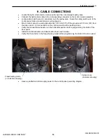
•
Locate the drive link connectors in both side columns.
•
Locate the three (3) nuts and the front connector plate from each connector.
•
Install panel #1 (panel with gasket at the bottom) into the opening. The three studs of the drive
link connectors must go through the slots of the drive links.
•
Loosely assemble the front connector plates and the hex nuts onto the connectors.
•
Insert two pins per side with the rounded end into the track (and install set screws).
•
Measure to ensure the panel is level. Tighten the hex nuts and the four (4) headless screws
within the front connector plates against the drive link.
Drive Link
Front Connector
Plate
Headless
Screw
Nut
Connector,
Front Half
Chain
Screw
Connector,
Back Half
Verify:
235 mm (9.25”) from
top of baseplate to
bottom of connector.
Same dimension on
the Motor side and
the Counterweight
side.
Summary of Contents for ThermicRoll
Page 2: ...Installation Instructions JAMISON DOOR COMPANY 2 H4494002 REV B...
Page 14: ...Installation Instructions JAMISON DOOR COMPANY 14 H4494002 REV B Pin Set Screw Pin Set Screw...
Page 27: ...Installation Instructions JAMISON DOOR COMPANY 27 H4494002 REV B 17 RADIO CONTROL RECEIVER...
Page 38: ...Installation Instructions JAMISON DOOR COMPANY 38 H4494002 REV B Notes...