58
13
Digital I/O
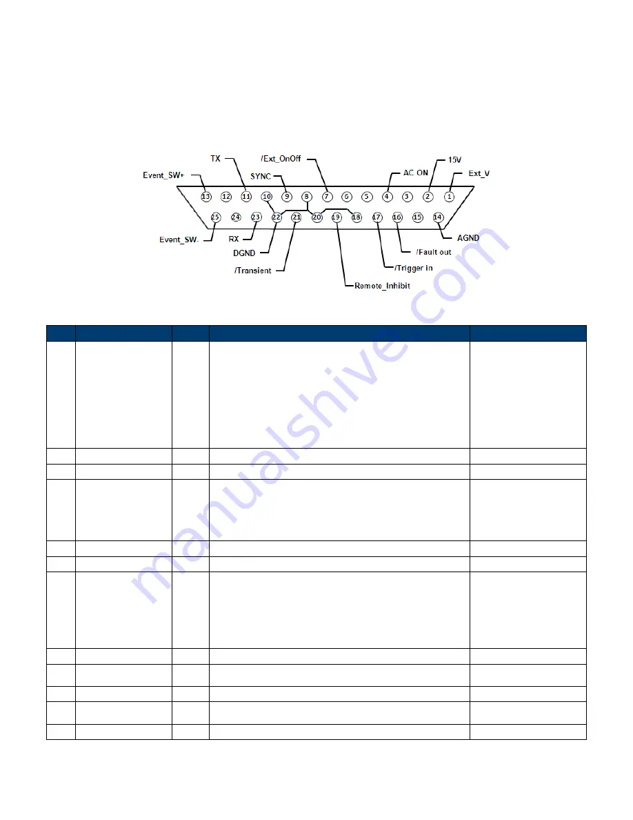
The digital I/O interface is used to control or monitor the Instrument. Refer to the figure below
describing the digital I/O 25-pin.
Figure 46 - Digital IO Pinout
Pin Name
I/O
Definition
Range
1
Ext_V
IN
External reference voltage input pin. (reference
ground: AGND)
In DC mode, enter -10V to +10V to control the
DC output.
In AC mode, enter 0 to +10V to control the AC
output.
Not supported in AC+DC mode.
-10 V to 10 V (DC)
0 to +10 V (AC)
2
15 VDC
OUT +15VDC output. (reference ground: AGND)
(15±0.8) V, 100 mA
3
NONE
4
AC ON
OUT When the output of the Instrument is active, the
voltage level of this pin is high (5V); otherwise
the voltage level is low (0V). (reference ground:
DGND)
5 V, 0 V, 1 mA
5
Reserved
Reserved
6
Reserved
Reserved
7
/Ext_OnOff
IN
This pin is used with Trigger_in (pin17).
When the voltage level of this pin is low, the
Instrument will stop output. When the voltage
level is high, the Instrument will start output.
(Refer to the description below for more details)
5 V
8
DGND
PWR Digital ground
9
/SYNC
OUT The synchronize signal
12 V
,
10 mA
10
DGND
PWR Digital ground
11
Tx
OUT RS232 transmitter
±9 V
,
10 mA
12
NONE
Summary of Contents for 9830B Series
Page 1: ...1 9830B Series USER MANUAL Model 9832B 9833B High Power Programmable AC Power Sources ...
Page 10: ...ix 2 Notations TEXT Denotes a softkey TEXT Denotes a front panel key ...
Page 28: ...15 6 Menu Tree ...
Page 86: ...73 THD 11 Harmonic 3 weight 21 3 THD 12 Harmonic 3 weight 24 5 ...
Page 88: ...75 THD 15 Harmonic 5 7 weight 2 45 3 95 THD 16 Harmonic 3 5 7 9 weight 11 4 05 2 1 3 ...
Page 89: ...76 THD 17 Harmonic 3 5 9 weight 7 17 3 42 0 8 THD 18 Harmonic 3 5 9 weight 8 11 3 48 1 ...
Page 95: ...82 THD 29 Harmonic 3 5 7 9 11 13 15 weight 33 3 20 13 8 10 8 8 5 7 2 5 5 ...


