Azatrax PFRR-3W Installation Manual Download Page 1

Installation guide, 'Pickle Fork' Back-and-Forth Model Train Controller 


 Azatrax model PFRR-3W


This controller can automate a 'back-and-forth' model train layout
with optional siding at either or both ends of the layout -- or, one
train can travel continuously around a loop, making stops at
predetermined locations.

Requirements:

Trains must be DC powered

, not DCC or AC, because train

direction is controlled by the polarity of the track power.

Maximum track current: 2 amps (2.5 amps for acceleration).

If turnouts (track switches) are used, the turnouts must be operated
by 

switch machines with 3-wire control cables

.  These are 'snap'

type switch machines with twin coils such as Atlas, Bachmann or
Peco.

If your turnouts have switch machines with 2-wire control cables,

use the Azatrax PFRR-2W control circuit.

An accessory power supply, 12 to 17 volts AC or DC is required to run the PFRR circuit.  This is separate from the track 
power.

This power supply must have sufficient current capacity to operate the switch machines -- typically 2 amps or more.

Train sensors:

One train sensor must be installed at each track location where a train is to stop.  One sensor is needed at each track end 
point.  Additional sensors or external detectors may be added for station stops where a train will momentarily stop, then 
continue in the same direction.

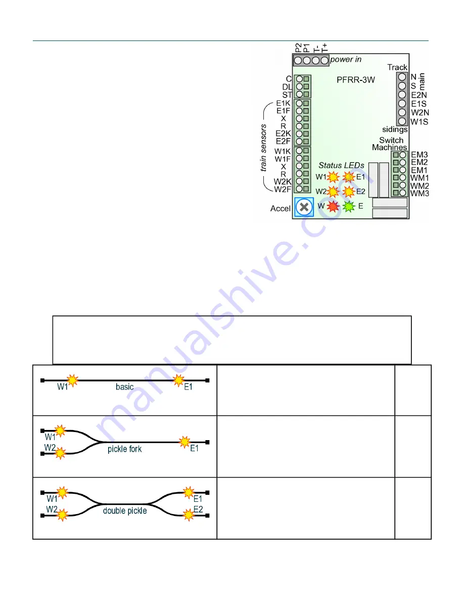
The PFRR controller has connections for up to four train sensors.  They are numbered W1, W2, E1 and E2.

The operating mode of the PFRR is determined by the combination of sensors that are connected.

So be careful to connect your sensors to the correct terminals on the PFRR controller.  The wrong

combination will result in unexpected operation.

Back and forth, no turnouts

Connect sensors:


Do not connect W2

W1 at west end
E1 at east end

E2 may be used as a station stop between W1 & E1. 
External detectors may also be used for station stops.

see

page

2

Back and forth, one turnout

Connect sensors:


Do not connect E2

W1 at west end, track 1
W2 at west end, track 2
E1 at east end

Use external detectors for station stops if desired.

see

page

2

Back and forth, two turnouts

Connect sensors:


W1 at west end, track 1
W2 at west end, track 2
E1 at east end, track 1
E2 at east end, track 2

Use external detectors for station stops if desired.

see

page

2

azatrax.com © 2017

Azatrax Pickle Fork RR Installation, 3-wire switch machines

rev. C1   pg. 1 of 7

Summary of Contents for PFRR-3W

Page 1: ...installed at each track location where a train is to stop One sensor is needed at each track end point Additional sensors or external detectors may be added for station stops where a train will momentarily stop then continue in the same direction The PFRR controller has connections for up to four train sensors They are numbered W1 W2 E1 and E2 The operating mode of the PFRR is determined by the co...

Page 2: ...omatically connect power to the track that is aligned with the switch points and cut off power to the other track If using power routing switches or no switches then no insulating rail gaps are needed Power only needs to be connected to the main track If your switches are not the power routing type one rail of each siding must be electrically isolated from the rest of the track This is done with a...

Page 3: ...rminals W2N and W1S Install insulated rail joiners or cut insulating gaps in all four rails where the loop ends meet the turnout Step 2 Install the Sensors Install train sensors at the locations shown above Leave space between the sensor and the end of the tail track so the train will be able to slow down and stop before reaching the end The rate of deceleration and acceleration is varied by turni...

Page 4: ...ve the track such as a bridge Angling the IR LED and its receiver toward each other is best for N and HO scale where the trains are close to the rail head and in places where an object above the track might cause false detections Angle the IR LED and receiver so their centerlines intersect at the height of the bottom of your rolling stock Tip 3 Track can be ballasted after sensors are installed Co...

Page 5: ...f the normally open switch or relay contact to the X and K terminals for the appropriate sensor A resistor must be connected in parallel with the detector switch Use 200 to 1000 ohms Test the sensors Connect an accessory power supply 12 17 volts AC or DC to terminals P1 and P2 If one side of the power supply is connected to a layout common or ground connect it to terminal P2 Connect the hot side t...

Page 6: ... also remembers the switch positions from the last operating session The PFRR uses this information to decide which train to run first ACCEL adjustment Turn the ACCEL adjustment clockwise for longer train acceleration and braking times Turn it counter clockwise for quicker starts and stops It is OK to let the train coast past the train detectors The PFRR will remember that a train passed the detec...

Page 7: ... to PFRR terminals ST and C Unlike mechanical switches used at the endpoints E1 E2 W1 and W2 the switches used as station detectors do not need a resistor connected to them Longer Delays The default pause time is six seconds This can be changed to 12 seconds by connecting a wire from terminal DL to C For other delay times connect a resistor or a 10k potentiometer to terminals DL and C A 10k resist...

Reviews: