900118,810165
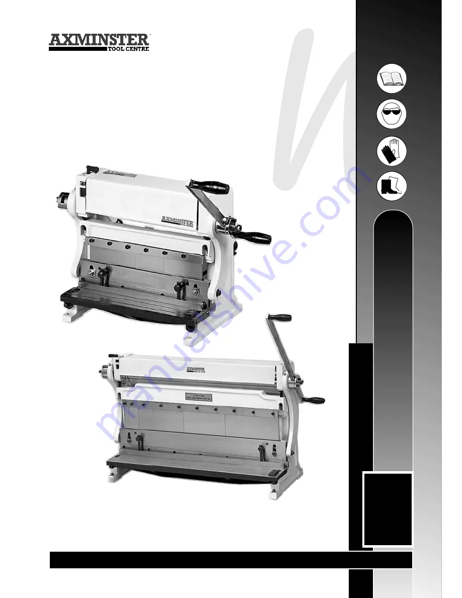
SSBP 305mm & RTC7030 750mm Sheet Metal Workers
Axminster Reference
No:
RTC7030 (810165)
SSBP (900118)
User Manual
W H I T E
A X M I N S T E R
W
w w w. a x m i n s t e r. c o . u k
RTC7030
(810165)
Page 1: ...8 810165 SSBP 305mm RTC7030 750mm Sheet Metal Workers Axminster Reference No RTC7030 810165 Axminster Reference No SSBP 900118 User Manual W H I T E AXMINSTER W www axminster co uk SSBP 900118 RTC7030 810165 ...
Page 2: ...mity 01 What s in the Box 02 General Safety Instructions 03 Specific Safety Instructions 03 Specifications 04 Assembly Instructions 04 Illustration Parts Description 05 06 Operating Instructions 07 08 09 10 Adjustments to the Sheet Metal Worker 11 Maintenance 12 Parts List 13 Parts Breakdown 14 PLEASE NOTE THE IMAGES IN THIS MANUAL SHOW THE SSBP SHEET METAL WORKER THE RTC7030 IS EXACTLY THE SAME B...
Page 3: ...Backstop Bar 2 off D Support Blocks 2 off E Support Locking Knobs 1 off Instruction Manual 1 off Guarantee Card Model Number RTC7030 1 off A 750mm Sheet Metal Worker 2 off B Support Rods 1 off C Backstop Bar 2 off D Support Blocks 2 off E Support Locking Knobs 1 off Instruction Manual 1 off Guarantee Card A B C D E A Fig 1 ...
Page 4: ...ay to minimise surface corrosion Before using the machine ensure that all locking nuts chucks etc are tightened and secure Check that all loose keys spanners etc have been removed Always ensure that long hair is tied back or retained by a band hat or safety helmet Remove all loose jewellery to prevent it from catching in rotating machinery Always check that the correct machining or cutting speed h...
Page 5: ...mm Steel 1 0mm Aluminium 1 5mm 25 51 75 152 203 254mm 38mm 1 020 x 410 x 510mm 130kg Assembly Instructions The bender comes secured to the base of the crate with four bolts these bolts can be used for mounting the bender to the workbench for safe and convenient operation The operating handle can be mounted on either side of the machine To re position the handle remove the handle securing plate see...
Page 6: ...tion Cover Lower roller Roller clearance adjusting keys Handle arm Handle Handle locking knob Lower bending die Right frame casting Cranking arm Pressure plate Work surface Guide block Upper roller Upper bending die Left frame casting Fig 3 Roller cover ...
Page 7: ... Illustration Parts Description FREEPHONE 0800 371822 Lower roller adjusting knobs Cross beam Back stop Back stop support block Back stop support rods Cranking arm Adjustment bar Adjustment bolt Fig 4 Upper roller Lower roller ...
Page 8: ...an be fitted to the right hand side of the table using hex screws see fig 8 The guide block should be set square to the lower blade using an engineer s square To carry out the shearing operation raise the cross beam to its highest position slide the material in between the blades position it correctly either with the marked line or up against the back stop and rotate the operating handle to make t...
Page 9: ...hrough the rollers by rotating the operating handle until contact is made with the rear roller Adjust the rear roller so that the work is slightly deformed as it passes through the rollers Make a series of passes through the rollers closing up the rollers each time until the required diameter is achieved The amount of bend that can be achieved per pass through the roll depends on the type and thic...
Page 10: ...R W Operating Instructions Guide block Hex bolt This part of the die has been removed Notch corners Bending Illustrations Workpiece Bolt Hex screw Fig 8 Fig 9 Fig 9a Fig 10 Fig 10a Fig 9b KEEP HANDS AWAY FROM DIE PRESS Die ...
Page 11: ...10 Grooves for wire and rod bending Lower roller Upper roller Workpiece Roller cover adjustment screw one each end of casting Lower roller adjustment knobs Rear roller Rolling Illustrations Fig 14 Fig 13 Fig 12 Fig 11 KEEP HANDS AWAY FROM ROLLERS ...
Page 12: ...djusted see fig 17 Loosen the screws which secure the work table to the frames and adjust the screws underneath the table until the two blades meet evenly along their length Re tighten the table securing screw see fig 17 Bending Die Adjustment If the line up of the upper dies becomes uneven for any reason they can be re aligned Cut a piece of hardwood to the same length as the dies ensuring that o...
Page 13: ...H I T E AXMINSTER W 12 Maintenance Grease the cranking arms using the grease nipples positioned on the tops of the arm see figs 18 18a Lightly grease the gears shown in fig 18b OIL Fig 18 Fig 18b Fig 18a ...
Page 14: ...13 W H I T E AXMINSTER W Parts List www axminster co uk ...
Page 15: ...W H I T E AXMINSTER W 14 Parts Breakdown FREEPHONE 0800 371822 ...
Page 16: ...cling Help to protect the environment take the packaging to the local amenity tip and place into the appropriate recycling bin Do not dispose of electric tools together with household waste material In observance of European Directive 2002 96 EC on waste electrical and electronic equipment and its implementation in accordance with national law electric tools that have reached the end of their life...