background image

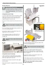
2) Turn the handle

to lock the table

Changing the Cutter Block Blades

30

11. If this appears satisfactory, go round and check everything 
is tight.  Lower the tables and re-lock them in place, refit the 
fence assembly, 80-81-82-83. 
 
12. Connect the machine to the main supply and continue 
with the operation.

Fig 80-81-82-83

Table locking bar

1) Push locking handle in

DISCONNECT THE MACHINE FROM THE MAINS 
SUPPLY BEFORE CONTINUING!

Spiral Cutter Blocks

The spiral cutter block has four rows of square cutters running 
around its circumference. There is 44 square cutters in total on 
the 10inch model and 56 cutters on the 12inch model. There is 
a blade machined to each side of the square cutter allowing the 
cutter to be rotated to a clean sharp edge if one side has been 
damaged or has become blunt, see fig 84-85. 
 
The square cutter has an embossed position marker to one 
of its four corners, once this mark has gone round one fall 
rotatation it is time to replace the square cutter.  
 
To rotate the cutter, loosen the Torx head screw and rotate until 
the new edge is in alignment with the other cutters. Re-tighten 
the Torx head screw to lock the cutter in place.

WARNING! BE VERY CAREFUL WHEN 
TURNING THE CUTTERS AS THE 
BLADES ARE EXTREMELY SHARP.

DO NOT OVERTIGHTEN TO AVOID THE TORX 
HEAD SCREW HEAD FROM GETTING
DAMAGED!

Position marker

Fig 84-85

Torx head screw  

Blade edge

Summary of Contents for AT260PT

Page 1: ...T PlanerThicknesser AT260PT Code 508498 AT260SPT Code 101156 AT310SPT Code 101157 Code 101157 with Spiral Blades Code 508498 with HSS Blades Code 101156 with Spiral Blades Original Instructions AT M 14 09 2018 BOOK REF 101612 ...

Page 2: ...td Axminster Devon EX13 5PH UK axminster co uk Type Planer Thicknesser Model AT260PT AT260SPT AT310SPT and conforms to the machinery example for which the EC Type Examination Certificate No BM 50314376 has been issued by Laizhou Futian Machinery Co Ltd at Fenghuang Science and Technology Park Development Zone Laizhou Shandong 261400 China and complies with the relevant essential health and safety ...

Page 3: ...ting bracket with clamping handle and two Cap head Screws G 2 Lift Shift Handles with M8 threads H 1 Cutter Block Side Guard I 1 NVR Emergency Stop Lever with two Phillips Screws and Nuts J 2 Fence Storage Angle Brackets K 1 Blade Setting Tool L 1 Push Guide Block M 2 Hex Keys 3 4 5mm N 1 Instruction Manual Quantity Item Code 101157 Part 1 Planer Thicknesser with Four Sided Spiral Blades B Model N...

Page 4: ...What s Included 4 C D F E G H I ...

Page 5: ...What s Included 5 L N K J M Continues Over ...

Page 6: ...he block Connect the dust extraction Ensure the hose will not foul any stuff being passed through the machine Check the height of the thicknessing table Engage the autofeed mechanism Periodically clean any excess build up of resin from the thicknessing table and apply any proprietary brand of lubricating agent NOTE Consideration should be given to the type of finish you will be applying to the sur...

Page 7: ...icknesser Capacity 190mm Max Planing Width 255mm Max Depth of Cut Thicknesser 2mm Max Depth of Cut Planer 4mm TCT Four Sided Spiral Knives Replaceable 44 TCT Length of Table 1 100mm Min Extraction Airflow Required 1 000m hr Noise Level 89dB Dust Extraction Outlet 100mm Overall L x W x H 1 100 x 660 x 940mm Weight 182kg Code 101157 Model AT310SPT Rating Trade Power 3 0kW 230V 1ph Feed Speed 5m min ...

Page 8: ... the tables Any movement is best carried out against the main frame cabinet Hoist the machine clear of the pallet slide the pallet out of the way and lower the machine in position NOTE There is four 10mm threaded holes to the underside of main frame to attach adjustable machine feet if required Check our catalogue or vist our website for details Fig 03 04 3 If you do not have the availability of s...

Page 9: ...4 Cutter Block Side Guard 1 Put to hand the side guard I remove the four Hex screws and washers to the front of the planer thicknesser and place safely to one side see fig 08 2 Place the side guard up against the frame covering the micro switch and cutter block drive shaft Line up the holes in the guard with the threaded holes in the frame and secure using the Hex screws and washers you removed ea...

Page 10: ...e two cap head screws see fig 16 17 Fig 16 17 2 Loosen the clamping handle on the mounting bracket insert the tilt assembly base plate E through the mounting bracket G sufficiently for the next step Lightly tighten clamping handle see fig 18 Fig 18 3 Locate the two lift and shift handles H and the fence F see fig 19 Position the fence up against the tilt assembly housing E Line up the pre drilled ...

Page 11: ...d shift handle has been removed to make it easier to screw on the threaded bolt Fig 22 23 Threaded bolt Handle Phillips screw spring Washer elongated slot H 6 Slide the fence F until it s stop is up against the tilt assembly housing E then tighten the lift and shift handles see fig 23 Fence stop Fence Storage Brackets 1 Locate the two fence storage brackets K Loosen the four cap head screw to the ...

Page 12: ...12 Machine Footprint Model AT260PT AT260SPT PlanerThicknesser 1100mm 600mm 940mm 705mm 1 000mm 1 385mm Model AT310SPT PlanerThicknesser ...

Page 13: ...ion hood Thicknessing table rise and fall control wheel NVR switch emergency control assembly Cutter block side guard Cutter block guard Main frame NVR switch assembly A Emergency stop shroud lever B B A Thicknessing table rise and fall clamping handle A Thicknessing table rise and fall control wheel B B A Thicknessing table rise and fall scale A Table Pointer B A B ...

Page 14: ...guard C Cutter block A Clamping Hex screws B Planer knife C Blade holder D Thicknessing Planing C A B A B C D Tilt fence assembly A Fence lift and shift clamping handles B Scale C Tilt clamping handle D Tilt stop A Adjusting nut B A B D A B B C Fence Stop A Fence stop clamping Hex screw B A B Table extension assembly A Table levelling adjusting bolts B Table clamping Hex bolts C A B C ...

Page 15: ...clamp Cutter block angle adjuster Fence securing clamping handle Fence support storage bracket Motor Drive access panel Motor securing bolts Emergency stop Outfeed table adjuster A A Emergency stop Fence angle pointer set to 45 A Pointer adjusting screw B A B ...

Page 16: ...adjuster Emergency stop Cutter block guard Outfeed table adjuster Cutter block side guard Cutter block Planer blade Blade holder Clamping grub screws Drive roller Pressure roller Anti kick back fingers Anti kick back fingers Dust extraction outlet Pull the spring clip back to release the extraction hood ...

Page 17: ...ble assembly Thicknessing table adjustable stop Table positioning studs A Table lock stud B Table locking bar A Four sided Spiral Cutter Block with TCT Spiral Blades Infeed table planning scale A B A Pointer Torx head screw Spiral cutter block Blade edges ...

Page 18: ...tension Infeed table locking handle Infeed table lifting handle Dust extraction hood Cutter block side guard Cutter block guard Main frame NVR switch assembly A and Emergency stop B A B Thicknessing table rise and fall scale Emergency stop control box with overload trip RESET switch Overload RESET switch ...

Page 19: ...icknessing fuction lever Thicknessing table Thicknessing table locking handle Digital thickness display Dust extraction hood Infeed table Table locking bar A Table micro switch B A B Surface table lifting handle Thicknessing table rise and fall control wheel Motor Drive access panel A A ...

Page 20: ...ht edge across the thicknessing table raise the table until the tip of the cutter block blade at it s lowest point is touching the top of the straight edge see fig A B Fig A B Fig C Fig D E 2 Using a vernier measure the height of the straight edge and write down the reading see fig C Loosen the grub screw holding the collar mechanisum turn the collar on the digital display unit and dial in the mea...

Page 21: ...g handle see fig 28 Fig 27 28 29 NOTE Check that the pointer on the tilt assembly lines up with zero on the scale If not loosen the pointer s clamping screw and adjust until correct see fig 29 NOTE Reset the 90 degree tilt stop by loosening the clamping nut and adjusting the Hex screw see fig 30 31 Tilt clamping handle 90 Square Scale Pointer Fig 30 31 Hex screws Clamping nut 90 tilt stop 2 Set th...

Page 22: ...orage brackets to the rear of the machine Unlock the infeed table locking handle and raise the table up see fig 37 38 39 With the table out of the way adjust the two positioning studs see fig 40 NOTE Remember to make small adjustments to the studs so you don t over correct 4 While holding the table pull out the table locking bar and lower the infeed table secure in place with the locking handle se...

Page 23: ... a straight edge across the thicknessing table and guide roller and check they are both in line with each other see fig 47 2 If adjustment is required loosen the two cap head bolts A and adjust the Hex bolts B until alignment is reached tighten the nuts C to lock the setting Re tighten the cap head bolts A see fig 48 Fig 48 Straight edge Table extension Guide roller A B C Ascertain the orientation...

Page 24: ...t the machine 5 When planing is finished switch off the machine by pressing the RED button and wait until it comes to a complete stop 1 Remove the fence assembly and place it in its holder to the rear of the machine Unlock the surface table and raise them to the upright position see fig 50 2 Rotate the dust extraction hood until it s in the upright position see fig 51 3 Raise the locking lever to ...

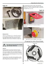
Page 25: ...te You will need to twist the mushroom shaped stop to unlock it allowing the machine to restart when the GREEN button is pressed Changing the Cutter Block Blades Overview The planer blades are mounted into three slot housings machined in the cutter block The slot housing comprises of a slot cut on a radial axis with a reverse tapered slot around it The depth of the first slot governs the seating o...

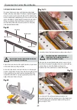
Page 26: ... 4 Remove the blade holder and lay aside Clean the slot housing thoroughly remove any resin build up sawdust chips etc Clean the blade holder and ensure the circumference of the cutter block is cleaned thoroughly see fig 59 Fig 59 5 Remove the new blade from its keeper and place the old blade in it s place Locate the blade setting tool L see fig 60 Fig 60 6 Introduce the blade holder position it a...

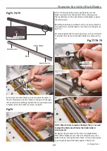
Page 27: ...that the blades are set at the correct height along the length of the cutter block by the following method below Find a scrap piece of timber and draw two measuring lines approximately 10mm apart see fig 65 Place the timber to one side of the cutter block across the tables and line up right measuring line to the edge of the outfeed surface table see fig 66 Rotate the cutter block so the blade tip ...

Page 28: ...of the slots is in the upright position Using a 4mm Hex key loosen the four cap head screws on the cutter block thus removing the clamping effect This should allow the blade to spring up protruding clear of the edge of the cutter block see fig 70 Fig 70 71 Fig 69 DISCONNECT THE MACHINE FROM THE MAINS SUPPLY BEFORE CONTINUING 4mm Hex key Cap head screw Blade 3 Carefully remove the blade and place s...

Page 29: ...k and the blade is against the setting recess 8 Holding the blade and setting tool L in position adjust the four grub screws until the blade is set at the correct height see fig 77 78 9 Securely tighten the four cap head screws in the cutter block to provide a firm clamp on the blade holder assembly see fig 79 Fig 77 78 79 NOTE When it s time to replace the blade there is no need to adjust the bla...

Page 30: ...nch model and 56 cutters on the 12inch model There is a blade machined to each side of the square cutter allowing the cutter to be rotated to a clean sharp edge if one side has been damaged or has become blunt see fig 84 85 The square cutter has an embossed position marker to one of its four corners once this mark has gone round one fall rotatation it is time to replace the square cutter To rotate...

Page 31: ...Daily checks Clean the machine thoroughly remove any shavings sawdust chips etc from in under and around the machine Check the cutter block for resin build up especially behind the blade and in the scallop of the blade holder Raise the tables and brush out and clean any debris or build up around the area of the noise attenuating slots in the edges of the overhand tables Check the infeed and take o...

Page 32: ...r cover plate Upper cover plate Drive belt Check the condition of the drive chains clean and apply a light coating of oil to the chains and sprockets Using Ambersil Dry PTFE Film Antistick spray 3 lubricate all the bearing areas taking care not to get oil on the drive belt and tyre surfaces Replace both machine covers plate Drive chain Sprocket Drive belt Re tightening table lock down handles If t...

Page 33: ...and lower cover plates lower the infeed and outfeed surface tables and lock them in place with the table locking handles Replace the fence assembly Motor assembly Drive belt Motor securing domed nuts washers CONNECT THE MACHINE TO THE MAINS SUPPLY Continue with operation ...

Page 34: ...Exploded Diagrams Lists 34 DIAGRAM A AT260PT AT260SPT PlanerThicknesser ...

Page 35: ...ex head M8x25 A 33 Set screw M8x50 A 37 Guard belt A 38 Guard belt left A 39 Guard belt right A 40 Fence bracket A 41 Nut hex M8 A 42 Cover plate friction wheel A 43 Flat washer 6mm A 44 Screw hex head M6x12 A 45 Flat washer 6mm A 46 Cap nut M7 A 49 Wave washer A 50 Wave washer A 51 Nut hex M10 A 52 Limit switch A 54 Pan head screw M4x30 A 55 Allen screw M5x10 A 56 Pan head screw M8x12 A 58 Transp...

Page 36: ...Exploded Diagrams Lists 36 AT260PT AT260SPT PlanerThicknesser DIAGRAM B ...

Page 37: ... Set screw M8x12 B 23 Allen screw M8x16 B 24 Allen screw M8x35 B 25 Spring washer 8mm B 27 Allen screw M6x55 B 28 Carriage bolt M6x40 B 29 Washer 6mm B 30 Pan head screw M4x10 B 31 Cross sunk head screw M4x8 B 32 Circle ring 18mm B 33 Roll pin 5x10 B 34 Collar B 35 Set screw M8x8 B 37 Roll pin 2 5x12 B 38 Hex nut M8 B 39 Support roller B 40 Hex head bolt M8x25 B 41 Flat washer 8mm B 42 Spring wash...

Page 38: ...Exploded Diagrams Lists 38 AT260PT AT260SPT PlanerThicknesser DIAGRAM C ...

Page 39: ...r 8mm C 25 Screw hex head M8x70 C 26 Collar C 27 Plastic washer C 28 Flat washer 8mm C 29 Hex head screw M8x45 C 30 Tension plate C 31 Flat washer 8mm C 32 Lock nut M8 C 33 Spacer C 34 Tension pulley C 35 Flat washer 8mm C 36 Hex head screw M8x45 C 37 Motor pulley C 38 Drive belt XPZ 1250 C 39 Drive chain 05B 1 172 C 40 Motor C 41 Set screw M8x10 C 42 Spring washer 6mm C 43 Allen screw M8x40 C 44 ...

Page 40: ...Exploded Diagrams Lists 40 AT260PT AT260SPT PlanerThicknesser DIAGRAM D ...

Page 41: ... house rear D 27 Bearing house front D 28 Shaft dust hood D 30 Glide piece D 31 Collar D 32 Set screw M6x6 D 33 Spacer D 34 Recoil lock D 35 Infeed roller D 36 Square spacer D 37 Pressure spring D 38 Sprocket A D 39 Spacer sprocket D 40 Flat washer 8mm D 41 Lock nut M8 D 42 Flat washer 6mm D 43 Pressure spring for rollers D 44 Lock nut M6 D 45 Flat washer 6mm D 46 Dust port D 47 Combined vacuum ho...

Page 42: ...Exploded Diagrams Lists 42 AT260PT AT260SPT PlanerThicknesser DIAGRAM E ...

Page 43: ...d out feed table E 7 Pan head screw M6x12 E 8 In feed table planer E 15 Screw E 16 Bracket E 17 Cap nut M6 E 18 Set screw M6x10 E 19 Set screw M6x6 E 20 Clamping lever E 22 Slide piece from table E 23 In Out feed table shaft E 25 Roll pin 6x35 E 26 External lock washer 10mm E 27 Wave washer E 30 Nut hex M10 E 32 Allen screw M10x35 E 33 Spring E 35 Nut hex M6 ...

Page 44: ... handle F 10 Insert board for fence F 11 Nut F 12 Set screw F 13 Scale F 14 Set screw F 15 Pan head screw F 16 Pointer F 17 Fence block F 18 Allen bolt F 19 Allen bolt F 20 Left fixing plate F 21 Sliding plate F 22 Allen screw F 23 Clamping plate F 24 Adjusting handle F 25 Right fixing plate F 26 Locking screw M6x12 F 27 Nut M6 F 28 Cross sunk head screew M6x12 F 29 Stop spacer F 30 Locking plate ...

Page 45: ...G 9 Knot G 10 Hex head screw M10x100 G 11 Washer 10mm G 12 Hex lock nut M10 G 13 Hex nut M8 G 14 Allen screw M6x20 G 15 Washer 6mm G 16 Hex lock nut M6 G 17 Flat washer 8mm G 18 Spring for guard G 19 Star knob screw M6x35 G 20 Star knob screw M8x35 G 21 Star knob for guard G 22 Cap nut M8 G 23 Allen screw M6x10 G 24 Pan head screw M5x65 G 25 Hex lock nut M6 G 26 Spacer G 27 Cross sunk head screw M...

Page 46: ...Exploded Diagrams Lists 46 DIAGRAM A AT310SPT PlanerThicknesser ...

Page 47: ... screw table A 26 Nut hex M16 A 27 Set screw M8x40 A 28 Washer 8mm A 29 Nut hex M8 A 30 Washer 8mm A 31 Nut hex M8 A 32 Screw hex head M8x25 A 33 Set screw M8x50 A 37 Guard belt A 38 Guard belt left A 39 Guard belt right A 40 Cover terminal box A 41 Nut hex M8 A 42 Cover plate friction wheel A 43 Flat washer 6mm A 44 Screw hex head M6x12 A 45 Flat washer 6mm A 46 Cap nut M7 A 49 Wave washer A 50 W...

Page 48: ...Exploded Diagrams Lists 48 DIAGRAM B AT310SPT PlanerThicknesser ...

Page 49: ...ad screw M6x12 B 19 Ring circle B 20 Handle wheel B 25 Insert table bolt B 26 Nut adjuse B 27 Wave washer B 28 Special thread B 29 Thin washer B 30 Nut hex M8 B 31 Scale rule B 32 Washer 6mm B 33 Spring washer 6mm B 34 Screw hex head M6x16 B 35 Roll pin 6x22 B 36 Scale body B 37 Flat washer 6mm B 40 Collar stop B 41 Set screw M6x6 B 42 Set screw M6x6 B 44 Support roller B 45 Hex head screw M8x25 B...

Page 50: ...Exploded Diagrams Lists 50 DIAGRAM C AT310SPT PlanerThicknesser ...

Page 51: ...C 25 Screw hex head M8x70 C 26 Collar C 27 Plastic washer C 28 Flat washer 8mm C 29 Hex head screw M8x45 C 30 Tension plate C 31 Flat washer 8mm C 32 Lock nut M8 C 33 Spacer C 34 Tension pulley C 35 Flat washer 8mm C 36 Hex head screw M8x45 C 37 Motor pulley C 38 Drive belt XPZ 1340 3Vx530 C 39 Drive chain 05B 1 172 C 40 Motor C 41 Set screw M8x10 C 42 Spring washer 6mm C 43 Allen screw M8x40 C 44...

Page 52: ...Exploded Diagrams Lists 52 DIAGRAM D AT310SPT PlanerThicknesser ...

Page 53: ...Nut hex M4 D 23 Screw hex w flange M8x40 D 24 Nut hex w flange M8 D 26 Bearing house rear D 27 Bearing house front D 28 Shaft dust hood D 30 Glide piece D 31 Collar D 32 Set screw M6x6 D 34 Recoil lock D 35 Infeed roller D 36 Square spacer D 37 Pressure spring D 38 Sprocket A D 39 Spacer sprocket D 40 Flat washer 8mm D 41 Lock nut M8 D 42 Flat washer 6mm D 43 Pressure spring D 44 Lock nut M6 D 45 ...

Page 54: ...Exploded Diagrams Lists 54 DIAGRAM E AT310SPT PlanerThicknesser ...

Page 55: ... screw M6x12 E 8 In feed table planer E 15 Screw E 16 Bracket E 17 Cap nut M6 E 18 Set screw M6x10 E 19 Set screw M6x6 E 20 Clamping lever E 21 Table turning handle E 22 Slide piece from table E 23 In Out feed table shaft E 25 Roll pin 6x35 E 26 External lock washer 10mm E 27 Wave washer E 28 Washer 8mm E 29 Nut hex M8 E 30 Nut hex M10 E 32 Allen screw M10x35 E 33 Spring E 35 Nut hex M6 ...

Page 56: ... 12 Screw hex head M10x120 F 13 Star knob for guard F 17 Star knob for guard F 18 Cap nut M8 F 19 Nut hex M8 F 20 Nut hex M8 F 21 Nut hex M8 thin F 22 Swivel base F 23 Large washer F 24 Sunk head screw M6x16 F 25 Lock nut M6 F 26 Washer 6mm F 27 Allen screw M6x20 F 28 Lock nut M6 F 31 Washer 10mm F 32 Lock nut M6 F 33 Washer 8mm F 34 Lock nut M8 F 35 Set screw M6x12 F 36 Spacer lock F 37 Sunk head...

Page 57: ...Adjusting handle G 8 Washer G 9 Adjusting handle G 10 Insert board for fence G 11 Nut G 12 Set screw G 13 Scale G 14 Set screw G 15 Pan head screw G 16 Pointer G 17 Fence block G 18 Allen bolt G 19 Allen bolt G 20 Left fixing plate G 21 Sliding plate G 22 Allen screw G 23 Clamping plate G 24 Adjusting handle G 25 Right fixing plate G 26 Locking screw M6x12 G 27 Nut M6 G 28 Cross sunk head screew M...

Page 58: ...Spiral Cutter Block Diagram 58 Spiral Cutter Block 10 Inch Spiral Cutter Block 12 Inch ...

Page 59: ...Wiring Diagrams 59 AT260PT AT260SPT DIAGRAM AT310SPT DIAGRAM ...

Page 60: ...s together with household waste material By law they must be collected and recycled separately EU Countries Only The Axminster guarantee is available on Craft Trade Engineer AirTools CNCTechnology Series machines Buy with confidence from Axminster So sure are we of the quality we cover all parts and labour free of charge for three years For more information visit axminster co uk 3years ...

Reviews: