Changing the Cutter Block Blades
27
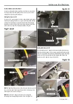
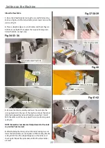
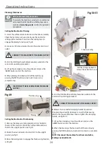
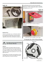
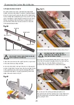
Fig 61-62-63-64
Blade
Setting recess
Locating feet
Blade holder
L
8. Repeat the procedure for the other two blades. When all
the blades are set at the correct height, carry out a quick check
by rotating the cutter block in reverse and visually inspecting
the edge of the blade against a fixed point.
9. If this appears satisfactory, go round and check everything
is tight and lower the surface tables and re-lock them in place.
Replace the fence assembly and continue with the operation.
NOTE: You can also check that the blades are set at the
correct height along the length of the cutter block by
the following method below.
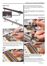
• Find a scrap piece of timber and draw two measuring lines
approximately 10mm apart, see fig 65.
• Place the timber to one side of the cutter block across the
tables and line up right measuring line to the edge of the
outfeed surface table, see fig 66.
• Rotate the cutter block so the blade tip pulls the timber
forward, stop when the blade detaches itself from the
timber.
• The rear line should now line up with the outfeed table’s
edge, see fig 67.
• Repeat for the opposite side.
NOTE: If there is any deviation along the length of the
cutter block, adjust the blade until correct.
Fig 65-66
10mm
Rear line
Outfeed table
Measuring line
Fig 67
Summary of Contents for AT260PT
Page 4: ...What s Included 4 C D F E G H I ...
Page 5: ...What s Included 5 L N K J M Continues Over ...
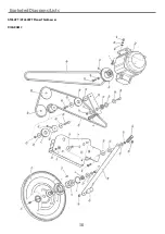
Page 34: ...Exploded Diagrams Lists 34 DIAGRAM A AT260PT AT260SPT PlanerThicknesser ...
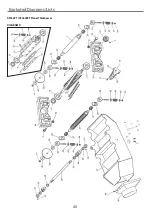
Page 36: ...Exploded Diagrams Lists 36 AT260PT AT260SPT PlanerThicknesser DIAGRAM B ...
Page 38: ...Exploded Diagrams Lists 38 AT260PT AT260SPT PlanerThicknesser DIAGRAM C ...
Page 40: ...Exploded Diagrams Lists 40 AT260PT AT260SPT PlanerThicknesser DIAGRAM D ...
Page 42: ...Exploded Diagrams Lists 42 AT260PT AT260SPT PlanerThicknesser DIAGRAM E ...
Page 46: ...Exploded Diagrams Lists 46 DIAGRAM A AT310SPT PlanerThicknesser ...
Page 48: ...Exploded Diagrams Lists 48 DIAGRAM B AT310SPT PlanerThicknesser ...
Page 50: ...Exploded Diagrams Lists 50 DIAGRAM C AT310SPT PlanerThicknesser ...
Page 52: ...Exploded Diagrams Lists 52 DIAGRAM D AT310SPT PlanerThicknesser ...
Page 54: ...Exploded Diagrams Lists 54 DIAGRAM E AT310SPT PlanerThicknesser ...
Page 58: ...Spiral Cutter Block Diagram 58 Spiral Cutter Block 10 Inch Spiral Cutter Block 12 Inch ...
Page 59: ...Wiring Diagrams 59 AT260PT AT260SPT DIAGRAM AT310SPT DIAGRAM ...

