AXIS Q1604 Network Camera
1 Tip
2 Ring
3 Sleeve
Audio Input
Microphone/Line in
Ground
Audio Output
Line out (mono)
Ground
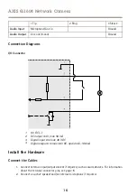
Connection Diagrams
I/O Connector
1
2
3
4
1
0 V DC (-)
2
DC output 3.3 V, max 50 mA
3
Digital input 0 to max 40 V DC
4
Digital output 0 to max 40 V DC, open drain, 100 mA
Install the Hardware
Connect the Cables
1. Connect external input/output devices if required, such as alarm devices. For information
about the terminal connector pins, see
.
2. Connect an active speaker and/or external microphone if required.
16
Summary of Contents for Q1604-E
Page 1: ...AXIS Q1604 Network Camera ENGLISH FRANÇAIS DEUTSCH ITALIANO ESPANÕL ò ò Installation Guide ...
Page 4: ......
Page 8: ...8 ...
Page 24: ...24 ...
Page 42: ...42 ...
Page 60: ...60 ...
Page 78: ...78 ...
Page 96: ...96 ...
Page 111: ...111 ...

