background image

GOT712S-837-24-110V User’s Manual 


Hardware and Installation


2.1 

Open back cover 

 
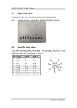
This section tells users how to open back cover. Please follow the steps below. 

 
Step 1 

Unscrew 12 screws on the back cover. Please refer the photo below. 


2.2 

Serial Ports Interface


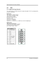
This  system  supports  RS-232/422/485  isolated  1.5KV  on  COM1~COM2  ports.  The  pin 
assignments are listed in table below. If you need to adjust these COM ports to work as RS-
232/422/485, please refer to BIOS setting in section 3.5. 


Pin 

RS-232   

RS-422 

RS-485 

NDCD 

TX- 

Data- 

NRX 

TX+ 

Data+ 

NTX 

RX+ 

No use 

NDTR 

RX- 

No use 

NDSR 

No use 

No use 

NRTS 

No use 

No use 

NCTS 

No use 

No use 

ISO1_GND 

ISO1_GND 

ISO1_GND 

Summary of Contents for GO712S-837-R-E3845-24-110VDC

Page 1: ...GO712S 837 R E3845 24 110VDC Railway 12 1 XGA TFT LCD PANEL PC User s Manual...

Page 2: ...manual Axiomtek reserves the right to change or revise this document and or product at any time without notice No part of this document may be reproduced stored in a retrieval system or transmitted in...

Page 3: ...ned technician is allowed to do so Integrated circuits on computer boards are sensitive to static electricity To avoid damaging chips from electrostatic discharge observe the following precautions Bef...

Page 4: ...2 4 Ethernet 9 2 5 DIO 10 2 5 1 Digital I O Specification 10 2 5 2 Digital I O Software Programming 11 2 5 3 Digital Input Wiring 12 2 5 4 Digital Output Wiring 13 2 6 Audio 13 2 7 CANBUS connector 14...

Page 5: ...v 3 6 Chipset Menu 27 3 7 Security Menu 30 3 8 Boot Menu 31 3 9 Exit Menu 32...

Page 6: ...vi This page is intentionally left blank...

Page 7: ...712S 837 is equipped with 12 1 TFT ruggedized touch panel computer and all lockable connectors are perfect choice for Human Machine Interface HMI in railway environments The 12 1 railway touch panel P...

Page 8: ...x RS 232 422 485 with isolated 1 5KV M12 A coded 2 x Gigabit LAN with isolated 1 5KV M12 X coded 2 x USB 2 0 M12 A coded 1 x DIO 6 input 2 output with isolated 1 5KV Phoenix type 1 x CAN bus with iso...

Page 9: ...ass IP65 NEMA4 aluminum front bezel Net Weight 3 Kgs 6 61 lb Dimension Main Body Size 330 x 61 5 x 245 mm Operation Temperature 40 to 70 Relative Humidity 10 to 95 40 Non Condensing Power Input 24V to...

Page 10: ...GOT712S 837 24 110V User s Manual 4 Introduction 1 3 Dimensions and Outlines The following diagrams show the dimensions and outlines of GOT712S 837...

Page 11: ...DC for power input with isolated 1 5KV 2 CAN Bus with isolated 1 5KV 3 Audio Line out Line in speaker out 4 DIO 6 input 2 output with isolated 1 5KV 5 USB 2 0 x 2 M12 A coded 6 COM 2 RS 232 422 485 wi...

Page 12: ...5 Packing List When you receive the GOT712S 837 the bundled package should contain the following items GOT712S 837 unit x 1 Phoenix Connector x 1 If you can not find the package or any items are missi...

Page 13: ...ich I O ports and flexible expansions for you to meet different demand The chapter will show you how to install the hardware It includes Open back cover Serial Ports USB Ports Ethernet DIO Audio CANBu...

Page 14: ...2 2 Serial Ports Interface This system supports RS 232 422 485 isolated 1 5KV on COM1 COM2 ports The pin assignments are listed in table below If you need to adjust these COM ports to work as RS 232...

Page 15: ...ction can be established by plugging one end of the Ethernet cable into this RJ 45 connector and the other end to a 1000 100 10 Base T hub with isolated 1 5KV Pin Definition 1 USB1_PWR 2 USB_DN1_C 3 U...

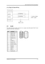
Page 16: ...ltage 0 to 30VDC at 25Hz Input level for dry contacts Logic level 0 close to ground Logic level 1 open Input level for wet contacts Logic level 1 3VDC max Logic level 0 10VDC min to 30VDC max source t...

Page 17: ...ardware and Installation 11 2 5 2 Digital I O Software Programming I2C to GPIO PCA9554PW GPIO Group0 5 0 is Output Group0 7 6 is Input I2C address 0b0100100x Registers Register 0 Input Group0 register...

Page 18: ...24 110V User s Manual 12 Hardware and Installation 2 5 3 Digital Input Wiring DRY contact Logic level 0 close to ground Logic level 1 open WET contact Logic level 1 3VDC max Logic level 0 10VDC min t...

Page 19: ...m supports one Audio Line out Line in speaker out with isolated 1 5KV The pin assignments are listed in table below Pin Definition 1 SPEK_OUTA 2 SPEK_OUTA 3 AUDIO_GND 4 AUDIO_OUT_L 5 AUDIO_OUT_R 6 NA...

Page 20: ...elow 2 8 DC Power connector The system supports one DC for power input with isolated 1 5KV The pin assignments are listed in table below Note 1 If the testing environment is not able to provide ACC pl...

Page 21: ...ards You can choose either slot 1 or slot 2 to install the wireless LAN card and refer to the following Step 1 Open the back cover and find out the mini card slot on main board Step 2 Insert the wirel...

Page 22: ...rovides one Mini card slot for user to install mSATA Please choose the slot 2 when installing the mSATA card and refer to the following instructions and illustration Step 1 Open the back cover and fin...

Page 23: ...D indication of the device 2 11 Auto dimming Because the human eye perceiving brightness is nonlinear PWM duty must be set percentage at each stage of opening and closing LCD Backlight Level 10 100 Le...

Page 24: ...GOT712S 837 24 110V User s Manual 18 Hardware and Installation This page is intentionally left blank...

Page 25: ...tup menu displays You can access the other setup screens from the main BIOS setup menu such as the Advanced and Chipset menus NOTE If your computer cannot boot after making and saving system changes w...

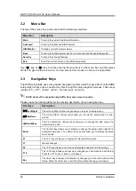
Page 26: ...F7 Enter ESC Arrow keys and so on NOTE Some of the navigation keys differ from one screen to another Please check the following table for the function description of each navigation key Hot Keys Desc...

Page 27: ...can be set up as described below The Main BIOS setup screen is shown below BIOS Information Display the auto detected BIOS information System Date Time Use this option to change the system time and da...

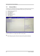
Page 28: ...can select any of the items in the left frame of the screen to go to the sub menus NCT6106D Super IO Configuration NCT6106D H W Monitor CPU Configuration IDE Configuration Miscellaneous Configuration...

Page 29: ...lue of the selected option Serial Port 1 2 configuration 1 Serial port This option used to enable or disable the serial port 2 Device Setting This item specifies the base I O port address and Interrup...

Page 30: ...s Manual 24 Drivers Installation NCT6106D H W Monitor This screen shows the Hardware Health Configuration CPU Configuration This screen shows the CPU Configuration and intel virtualization technology...

Page 31: ...lect options for the SATA Configuration and change the value of the selected option SATA Mode Use this item to choose the SATA operation mode Here are the options for your selection IDE Mode AHCI Mode...

Page 32: ...GOT712S 837 24 110V User s Manual 26 Drivers Installation CSM Configuration Enable is Legacy mode Disable is UEFI mode USB Configuration Display USB Device Configuration...

Page 33: ...Menu In this section it will display the available devices on your system for you to configure the boot settings and the boot priority North Bridge This screen shows the North Bridge memory informati...

Page 34: ...GOT712S 837 24 110V User s Manual 28 Drivers Installation South Bridge...

Page 35: ...GOT712S 837 24 110V User s Manual AMI BIOS Setup Utility 29 USB Configuration Only support USB2 0 EHCI...

Page 36: ...GOT712S 837 24 110V User s Manual 30 Drivers Installation 3 7 Security Menu In this section you may set change or clear the supervisor user password for the system...

Page 37: ...e Timeout for wait press key to enter Setup Menu Bootup NumLock State Use this item to select the power on state for the NumLock The default setting is on Quiet Boot Use this item to enable or disable...

Page 38: ...GOT712S 837 24 110V User s Manual 32 Drivers Installation 3 9 Exit Menu NOTE Load default before updating g TXE firmware and restart...

Reviews: