Axioma LEZ UAB
ULTRASONIC WATER METER
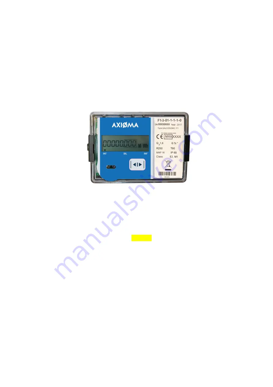
QALCOSONIC F1
TECHNICAL DESCRIPTION, INSTALLATION AND USER INSTRUCTIONS
PLF1V04
KAUNAS
Page 1: ...Axioma LEZ UAB ULTRASONIC WATER METER QALCOSONIC F1 TECHNICAL DESCRIPTION INSTALLATION AND USER INSTRUCTIONS PLF1V04 KAUNAS...
Page 2: ...as waste electronic equipment in terms of the European Directive 2012 19 EU WEEE Marking of electrical and electronic equipment in accordance with Article 14 2 of Directive 2012 19 EU This symbol on...
Page 3: ...rmetic fitting of primary flow and temperature sensors into the pipeline Reliable fastening of water meter at installation Warning Mounting of the sub assemblies of water meter is permissible only aft...
Page 4: ...65 L 300mm brass housing 08 DN65 L 300mm steel housing 8S DN80 L 350mm brass housing 09 DN80 L 350mm steel housing 9S DN80 L 300mm brass housing 19 DN100 L 350mm brass housing 10 DN100 L 350mm steel h...
Page 5: ...190 P 63 G1 1 4 or DN25 260 P 25 6 3 R400 7 875 0 016 0 026 0 008 G1 or DN20 190 P 63 10 R250 12 5 0 04 0 064 0 02 G1 1 4 or DN25 260 P 63 G2 or DN40 300 P 25 10 R400 12 5 0 025 0 04 0 012 G1 1 4 or...
Page 6: ...lay parameters measurement units and operation modes The following information can be displayed integral and instantaneous measured parameters and archive data and device configuration information lis...
Page 7: ...sible current up to 20mA voltage up to 50V Pulse duration 125 ms in the normal operating mode 1 2 ms in the test mode Pulse values on pulse output device in the operating mode as specified in the tabl...
Page 8: ...R Q3 Q1 maximum admissible working pressure and voltage level for external power supply end connections of the flow sensor Marking of Flow sensors There are following information on the flow sensor Ar...
Page 9: ...e calculator communication module can be installed and must be connected Connector of the communication module is set in a calculator connector The module is fastening with two screws Connection of th...
Page 10: ...sor can be mounted both vertically and horizontally in pipelines or on an incline Necessary condition in normal working mode pipeline must be under pressure and fully filled with water The location an...
Page 11: ...water meter is equipped with 8 digits LCD Liquid Crystal Display with special symbols to display parameters measurement units and operation modes Destination of the special symbols the flow is flowing...
Page 12: ...one error has been detected error codes 1 1 are displayed if the button has not been activated for more than 60 seconds After 60 seconds past the LCD is automaticly switching to permanent display mod...
Page 13: ...ustomer number INT INF BIL Corresponds to a wire transmission via MBus protocol 1 10 Control number INT INF BIL 1 11 Error code If parameter 1 1 not indicated 1 12 Flow rate 1 13 Next replacement date...
Page 14: ...Forvard volume of previous month with date stamp INT INF BIL Total volume of previous month if revers volume mode is activ Changing with date stamp every 1 second 2 8 Revers volume of previous month...
Page 15: ...previous month only to display the data of the last two months or to display the data of all 36 previous months 3 1 Flow rate 3 2 Temperature if used INT INF BIL 3 3 Next replacement date of the batt...
Page 16: ...way it is possible to switch off indication of irrelevant parameters 6 3 2 Viewing the readings in TEST mode Service menu The menu structure in a test mode is presented in the Fig 6 2 4 5 4 4 4 6 4 7...
Page 17: ...ted more than one error 3 corresponds errors 2 1 5 corresponds errors 4 1 7 corresponds errors 4 2 1 9 corresponds errors 8 1 A corresponds errors 8 2 B corresponds errors 8 2 1 C corresponds errors 8...
Page 18: ...again The readings of meter in verification test mode are presented in p 6 3 2 LCD resolution in verification mode TEST is 00 000001 m 3 Volume pulse values in verification mode TEST are presented in...
Page 19: ...STORAGE REQUIREMENTS Packed meters may be transported in any type of covered vehicle Equipment should be anchored reliably to avoid shock and possibility to shift inside vehicle Meters should be prote...
Page 20: ...PEF1IP68V04 2017 11 20 20 Annex A Fig A1 Electrical wiring diagrams V1 additional pulse input output 1 V2 additional pulse input output 2 T additional temperature sensor if used...
Page 21: ...Out1 5 Terminal for temperature sensor If temperature sensor is used 6 Terminal for temperature sensor If temperature sensor is used Terminal no Destination 20 CL CL module 21 CL CL module 24 25 M bu...
Page 22: ...sions of calculator B2 Sizes and dimensions of water meter QALCOSONIC F1 Fig B2 1 Threaded end connections G3 4 Fig B2 2 Threaded end connections G1 mounting length L 110 mm or 105 165 mm mounting len...
Page 23: ...PEF1IP68V04 2017 11 20 23 Annex B continued a b Fig B2 4 Mounting length L 260 mm a Threaded end connections G1 1 4 b Flanged end commections DN25...
Page 24: ...PEF1IP68V04 2017 11 20 24 Annex B continued a b c B2 5 pav Mounting length L 300 mm a Threaded end connections G2 b c Flanged end commections DN40 two design options...
Page 25: ...F1IP68V04 2017 11 20 25 Annex B continued a Dimensions of flow sensors DN50 MAP16 MAP25 DN65 MAP16 Brass housing b Dimensions of flow sensors DN65 MAP25 DN80 MAP16 MAP25 DN100 MAP16 MAP25 Brass housin...
Page 26: ...iga c Dimensions of flow sensors DN65 MAP16 MAP25 DN80 MAP16 MAP25 DN100 MAP16 MAP25 Steel housing Fig B2 6 Flanged end connections DN50 DN65 DN80 DN100 L D D1 H B DN65 300 180 145 180 205 DN80 350 19...
Page 27: ...seal 3 mounting seal after installation a Sealing of flow sensor b Sealing of flow sensor with end connections G 3 4 G1 DN20 with end connections G1 1 4 DN25 DN32 1 1 1 1 c Sealing of flow sensor wit...