AXIOHM, 1-9 Rue d’Arcueil
BP 675, 92542 Montrouge Cedex, France
Tel : (33) (0) 1 47 46 78 00 Fax (33) (0) 1 46 55 13 44
1 / 25
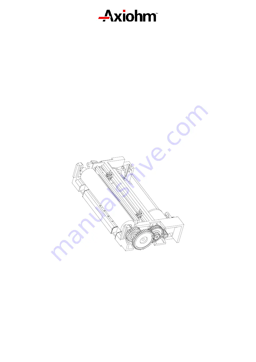
THERMAL PRINTER MECHANISM
USER'S MANUAL
THTN Series
Reference : FDE – 3106531 issue-Z
January - 01
Page 1: ...IOHM 1 9 Rue d Arcueil BP 675 92542 Montrouge Cedex France Tel 33 0 1 47 46 78 00 Fax 33 0 1 46 55 13 44 1 25 THERMAL PRINTER MECHANISM USER S MANUAL THTN Series Reference FDE 3106531 issue Z January...
Page 2: ...User s Manual page 2 25 Ref FDE 3106531 Z IMPORTANT This manual contains the basic instructions to run your printer Read it carefully before using your printer paying full attention to the section Rec...
Page 3: ...cifications of 64 bits LSI driver 11 4 3 3 Print head connection 13 4 4 BIPOLAR STEPPING MOTOR 14 4 4 1 Characteristics 14 4 4 2 Motor connection 14 4 4 3 Induction sequence and timing paper feed 15 4...
Page 4: ...nting method Static thermal dot line printing Number of resistor dots 384 Resolution 8 Dots mm Printing width 48 mm Paper width 58 or 60 mm Head T detection Thermistor Paper feed pitch 2 Motor steps 0...
Page 5: ...g Recommended paper JUJO TF50KSE3 Maximum paper thickness 80 g m 2 with front paper path 130 g m 2 with underneath paper path For underneath paper path this value can be overshot with restrictions if...
Page 6: ...elf threading screws pan head eco syn length 6 mm for example from our supplier BOSSARD for the 3 diameters 2 2 0 05 3 4 Cover switch position The cover must contain a spur to activate the switch its...
Page 7: ...of dots 11 1 5 mm n Distance between opto sensor and cut line with tear bar 14 1 5 mm n Tow positions for opto sensor Middle lateral position 30 15 mm from paper path guide Set on right side at 19 5 m...
Page 8: ...t 2 activated phases 544 mA 4 3 Description of print head Printer THTN Driver chips 6 Operating range Vcc 2 7 to 5 5 1 V DC Mean dot resistance 4 173 Nominal dot supply voltage 5 min 3 max 8 5 V DC No...
Page 9: ...nes Undetermined states can happen and destroy the head The power source should be disconnected from the logic source The logic source must be connected to the same source as the electronic circuits i...
Page 10: ...e signals on the printer connection OUT CLK Strobe IN SI SO SI SO Resistors Resistors R64 R1 R64 R1 OE n OE n 1 CHIP n CHIP n 1 Figure 2 Routing of data to the thermistor dots paper path direction Fig...
Page 11: ...are should be taken to filter any transient signal or parasitic in order to keep the driver in a known state failure to observe this may result in head destruction Clock frequency max 8 MHz 4 5 to 5 5...
Page 12: ...data into memory active on logic level 0 rest level logic 1 OE Output Enable OE1 to OE6 power activation signals active at logic level 1 Data Out n Internal data out to heating points not available on...
Page 13: ...18 Vdd 19 CLOCK Clock signal for serialising data to line 20 STROBE Strobe signal for line print 21 Data out Data out 22 Vch 23 Vch 24 B0 Paper feed motor B0 25 A0 Paper feed motor A0 26 A1 Paper fee...
Page 14: ...Coil Resistance 18 Number of phases 2 bipolar Pitch angle 18 Number of steps per revolution 20 Paper feed for 2 motor steps 0 125 mm Recommended control current 277 5V 18 mA phase Maximum starting sp...
Page 15: ...he same current during t1 1 ms It must be followed by 16 motor steps in order to compensate the play in the gears 4 4 4 Printing mode There are 4 different positions for the motor phases The circulati...
Page 16: ...and 12 Switch Door closed open open closed 4 5 2 End of paper opto sensor This opto sensor detects the end of paper 4 5 2 1 Electrical characteristics Absolute maximum ratings IF mA VR V PD mW VCEO V...
Page 17: ...external circuit 47K Vo PRINTER OPTO SENSOR VCC 5V if Condition For If 20 mA Output signal is LOW when paper is PRESENT Vo 0 7V Output signal is HIGH when paper is EXHAUSTED Vo 3 4V 4 5 3 2 Sample ext...
Page 18: ...ating cycle thereby permitting a high speed to be achieved in this mode it is recommended to use historical control see chapter Heating Time End of printing Transmission of data in series Din in step...
Page 19: ...quality printing End of printing Heating controlled through OE 1 OE 2 OEn simultaneously Transfer to memory stage STROBE Transmission of data in series Din in step with CLK Printing of n dot line Tra...
Page 20: ...of the line at a time effectively giving reduced consumption Heating controlled through OE 1 OE 2 OEn successively or in blocks End of printing Transfer to memory stage STROBE Transmission of data in...
Page 21: ...or a longer period than the specified maximum burning out the heated resistor To avoid this we recommend applying the heating voltage Vch after the logic supply voltage Vcc 5V The same precaution shou...
Page 22: ...3 printer cannot be operated How to use tables Without historical control apply the indicated heating time given as a function of speed voltage and temperature At high speed printing quality for isola...
Page 23: ...0 960 6 Volts 50 C 1 610 1 450 1 330 1 230 1 070 1 000 0 940 0 840 6 5 Volts 0 C 2 370 2 140 1 950 1 810 1 570 1 470 1 390 1 240 6 5 Volts 10 C 2 170 1 960 1 790 1 650 1 440 1 350 1 270 1 130 6 5 Volt...
Page 24: ...tant Max 30 sec in air This thermistor has a rated value of 30 k 5 Its resistance variation can be expressed as follows R Rn exp B 1 T 1 Tn where T is in Kelvin degrees K This gives the following curv...
Page 25: ...ng chart 12 drivers 11 duty cycle 5 F flex cable 13 H Heating current 8 Heating time 22 historical control 22 L Logic current 8 M memory register 9 motor 14 21 motor driving 21 O opto sensor 16 17 P p...