background image

37 


ENGF-107 REV. A 01/11 


          © 2011 AXEON Water Technologies 

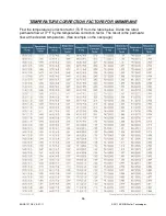
If a system is rated to produce 5 gpm of permeate water @ 77˚ F. The same system will 

produce more water at a higher temperature. It will also produce less water at a lower 

temperature.  Use the temperature correction table to obtain the correct flow. 


Example: 


5 gpm @ 59˚ F (5÷1.42=3.52 gpm) 

5 gpm @ 77˚ F (5÷1=5 gpm) 

5 gpm @ 84˚ F (5÷0.89=5.62 gpm) 


SERVICE ASSISTANCE 

If service assistance is required, please complete the following process: 
Contact your local dealer or distributor.  Prior to making the call, have the following 
information available:  system installation date, serial number, daily log sheets, current 
operating parameters (e.g. flow, operating pressures, pH, etc.), and a detailed 
description of the problem. 


Summary of Contents for CT-4000

Page 1: ...Reverse Osmosis User s Manual Model CT 4000 CT 5000 CT 7000 CT 7000 Pictured...

Page 2: ...2 ENGF 107 REV A 01 11 2011 AXEON Water Technologies This Page Left Blank...

Page 3: ...EM IDENTIFICATION 15 CT 4000 MEMBRANE FLOW DIAGRAM 20 CT 5000 MEMBRANE FLOW DIAGRAM 21 CT 7000 MEMBRANE FLOW DIAGRAM 22 SYSTEM PURGING 23 INITIAL START UP 24 DESIGN BASIS FOR CT 4000 CT 5000 CT 7000 2...

Page 4: ...OG MUST BE MAINTAINED AND COPIES WILL NEED TO BE SENT TO YOUR LOCAL DEALER OR DISTRIBUTOR FOR REVIEW NOTE PRIOR TO OPERATING OR SERVICING THE REVERSE OSMOSIS SYSTEM THIS USER S MANUAL MUST BE READ AND...

Page 5: ...NOTE HIGHER TDS AND OR LOWER TEMPERATURES WILL REDUCE THE SYSTEM S PRODUCTION REJECTION RECOVERY FLOW RATES CT Series reverse osmosis systems are designed to produce permeate water at the capacities...

Page 6: ...rmula Recovery Product Water Flow Rate Feed Water Flow Rate x 100 Example 40 2 78 7 0 x 100 NOTE ALL FLOW RATES MUST BE EXPRESSED IN THE SAME UNITS TYPICALLY GALLONS PER MINUTE GPM SYSTEM REQUIREMENTS...

Page 7: ...GGRESSIVE TO SOME PLUMBING MATERIALS SUCH AS COPPER PIPING CONCENTRATE WASTE WATER CONNECTION Locate the 1 connection labeled concentrate and attach to a drain Run the concentrate line to an open drai...

Page 8: ...all it at this time PRE FILTRATION CT Series systems are supplied with a 5 micron sediment filter 10 micron carbon block and a 1 micron sediment filter Change the cartridge once a month or when a 10 1...

Page 9: ...system s model and pump size MOUNTING The free standing system should be bolted down in compliance with local regulation standards or securely fastened MEMBRANE ELEMENTS CT Series reverse osmosis sys...

Page 10: ...10 ENGF 107 REV A 01 11 2011 AXEON Water Technologies HF1 STANDARD...

Page 11: ...11 ENGF 107 REV A 01 11 2011 AXEON Water Technologies HF4 OPTIONAL...

Page 12: ...12 ENGF 107 REV A 01 11 2011 AXEON Water Technologies HF5 OPTIONAL...

Page 13: ...13 ENGF 107 REV A 01 11 2011 AXEON Water Technologies NF3 OPTIONAL...

Page 14: ...14 ENGF 107 REV A 01 11 2011 AXEON Water Technologies NF4 OPTIONAL...

Page 15: ...15 ENGF 107 REV A 01 11 2011 AXEON Water Technologies CT 4000 CT 5000 CT 7000 SYSTEM IDENTIFICATION FIGURE 1A...

Page 16: ...Controls RO system 10 Recycle Valve Recycles concentrate back to feed If Applicable 11 Concentrate Valve Controls flow of concentrate waste water to the drain 12 RO Pump Motor Pressurizes RO System 13...

Page 17: ...17 ENGF 107 REV A 01 11 2011 AXEON Water Technologies FIGURE 1B FIGURE 1C...

Page 18: ...18 ENGF 107 REV A 01 11 2011 AXEON Water Technologies FIGURE 1D FIGURE 1E...

Page 19: ...19 ENGF 107 REV A 01 11 2011 AXEON Water Technologies FIGURE 1F Note A portion of the frame has been removed to expose components...

Page 20: ...20 ENGF 107 REV A 01 11 2011 AXEON Water Technologies CT 4000 MEMBRANE FLOW DIAGRAM FIGURE 1G Note Black arrows represent concentrate water and white arrows represent permeate water...

Page 21: ...21 ENGF 107 REV A 01 11 2011 AXEON Water Technologies CT 5000 MEMBRANE FLOW DIAGRAM FIGURE 1H Note Black arrows represent concentrate water and white arrows represent permeate water...

Page 22: ...22 ENGF 107 REV A 01 11 2011 AXEON Water Technologies CT 7000 MEMBRANE FLOW DIAGRAM FIGURE 1I Note Black arrows represent concentrate water and white arrows represent permeate water...

Page 23: ...S PROCEDURE 1 Redirect permeate water to the drain for this procedure 2 Fully open the concentrate valve 11 Counter Clockwise Figure 1B Page 16 3 Fully close the recycle valve 10 Clockwise If Applicab...

Page 24: ...cle valve 10 If Applicable and the throttle valve to the designed flow and pressure Figure 3 Page 27 7 Inspect the system for leaks 8 Allow the system to run for one hour to flush the preservative sol...

Page 25: ...25 ENGF 107 REV A 01 11 2011 AXEON Water Technologies DESIGN BASIS FOR CT 4000 CT 5000 CT 7000 WARNING NEVER EXCEED THE MAXIMUM PRESSURE RATING OF YOUR SYSTEM...

Page 26: ...Shut down the system for extended periods Close the throttle valve completely Operate the system with insufficient feed flow Operate the pump dry OPERATION MAINTENANCE The reverse osmosis process cau...

Page 27: ...URE SWITCH The low pressure switch shuts off the system when the feed water pressure drops below 15 PSI preventing damage to the pump The system restarts automatically when there is a constant pressur...

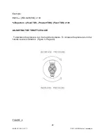
Page 28: ...ogies Example 98 5 550 8 25 550 x 100 Rejection Feed TDS Product TDS Feed TDS x 100 ADJUSTING THE THROTTLE VALVE To decrease the pressure turn the handle clockwise To increase the pressure turn the ha...

Page 29: ...f necessary 4 Make sure that all parts are clean and free from dirt Examine the brine seal and permeate tube for nicks or cuts Replace the O rings or brine seal if damaged 5 Flow directions should be...

Page 30: ...f necessary 5 With a smooth and constant motion push the membrane element into the housing so the brine seal enters the housing without coming out of the brine seal groove 6 Re install the end caps by...

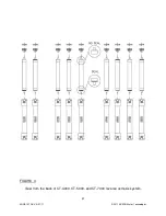
Page 31: ...31 ENGF 107 REV A 01 11 2011 AXEON Water Technologies FIGURE 4 View from the back of CT 4000 CT 5000 and CT 7000 reverse osmosis system...

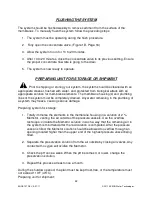
Page 32: ...g lines of the system must be completely drained Any water remaining in the plumbing of a system may freeze causing serious damage Preparing system for storage 1 Totally immerse the elements in the me...

Page 33: ...e housings removing the pre filter cartridges and drain the water from the housings 7 Disconnect the tubing from the connectors on the permeate and concentrate inlets and outlets 8 Fully open the conc...

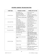
Page 34: ...ane Replace membrane Exceeding maximum feed water temperature See temperature correction sheet Poor permeate quality Low operating pressure See low inlet pressure Damage product tube o rings Inspect a...

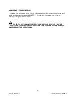
Page 35: ...thin 20 of the rated production after correcting the feed water temperatures above or below 77 F Check your permeate flow meter to determine the permeate flow rate NOTE TO DETERMINE THE TEMPERATURE CO...

Page 36: ...RE CORRECTION FACTORS FOR MEMBRANE Find the temperature correction factor TCF from the table below Divide the rated permeate flow at 77 F by the temperature correction factor The result is the permeat...

Page 37: ...to obtain the correct flow Example 5 gpm 59 F 5 1 42 3 52 gpm 5 gpm 77 F 5 1 5 gpm 5 gpm 84 F 5 0 89 5 62 gpm SERVICE ASSISTANCE If service assistance is required please complete the following process...

Page 38: ...Of ____________________ System Serial ____________________ Date Time Hour of Operation Filter inlet pressure psi Filter outlet Pressure psi Concentrate Pressure psi Pump Discharge Pressure psi Feed F...

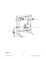
Page 39: ...39 ENGF 107 REV A 01 11 2011 AXEON Water Technologies DRAWINGS FIGURE 5...

Page 40: ...40 ENGF 107 REV A 01 11 2011 AXEON Water Technologies FIGURE 6...

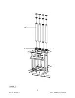
Page 41: ...41 ENGF 107 REV A 01 11 2011 AXEON Water Technologies FIGURE 7...

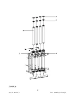
Page 42: ...42 ENGF 107 REV A 01 11 2011 AXEON Water Technologies FIGURE 8...

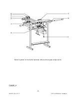
Page 43: ...43 ENGF 107 REV A 01 11 2011 AXEON Water Technologies Note A portion of the frame has been removed to expose components FIGURE 9...

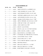
Page 44: ...E LOW N O 15 30 1 4 FNPT 8 1 200789 PUMP MULTI STAGE 1 5HP 110 220V 1PH 9 1 200994 VALVE GLOBE SS 3 4 FNPT 10 4 200379 MEM HF1 4040 SYSTEMS 11 4 200527 MHS PVC 4040 1 2 x 1 2 SP FNPT SYSTEMS 12 2 2008...

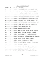
Page 45: ...E LOW N O 15 30 1 4 FNPT 8 1 200789 PUMP MULTI STAGE 1 5HP 110 220V 1PH 9 1 200994 VALVE GLOBE SS 3 4 FNPT 10 4 200379 MEM HF1 4040 SYSTEMS 11 4 200527 MHS PVC 4040 1 2 x 1 2 SP FNPT SYSTEMS 12 2 2008...

Page 46: ...E LOW N O 15 30 1 4 FNPT 8 1 200789 PUMP MULTI STAGE 1 5HP 110 220V 1PH 9 1 200994 VALVE GLOBE SS 3 4 FNPT 10 4 200379 MEM HF1 4040 SYSTEMS 11 4 200527 MHS PVC 4040 1 2 x 1 2 SP FNPT SYSTEMS 12 2 2008...

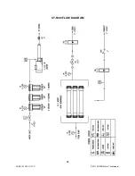
Page 47: ...47 ENGF 107 REV A 01 11 2011 AXEON Water Technologies CT 4000 FLOW DIAGRAM...

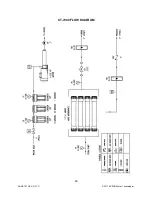
Page 48: ...48 ENGF 107 REV A 01 11 2011 AXEON Water Technologies CT 5000 FLOW DIAGRAM...

Page 49: ...49 ENGF 107 REV A 01 11 2011 AXEON Water Technologies CT 7000 FLOW DIAGRAM...

Page 50: ...50 ENGF 107 REV A 01 11 2011 AXEON Water Technologies 110 220V 50 60 Hz 1 PHASE ELECTRICAL SCHEMATIC Minitrol...

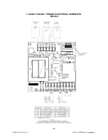
Page 51: ...51 ENGF 107 REV A 01 11 2011 AXEON Water Technologies 208 220V 50 60 Hz 3 PHASE ELECTRICAL SCHEMATIC Minitrol...

Page 52: ...52 ENGF 107 REV A 01 11 2011 AXEON Water Technologies 110 220V 50 60 Hz 1 PHASE ELECTRICAL SCHEMATIC Minitrol IF...

Page 53: ...53 ENGF 107 REV A 01 11 2011 AXEON Water Technologies 208 220V 50 60 Hz 3 PHASE ELECTRICAL SCHEMATIC Minitrol IF...

Page 54: ...54 ENGF 107 REV A 01 11 2011 AXEON Water Technologies...

Reviews: