background image


www.avonic.eu 


35 

LAN Access and Control


IP camera default IP address"192.168.100.88" 

user "admin", password "admin".  


To find camera IP, press * and # and 4 on remote controller one by one, IP address will be 

shown on screen. 

Change IP address: 

On web control page, find "Network"--->Change IP---->Click "Apply"----> Restart camera 


Visit/Access IP Camera 

Input http://192.168.100.88 to web browser, a login window pop up, input  

login name: admin 

password: admin 

Summary of Contents for CM60-IPU

Page 1: ...Avonic CM60 IPU Full HD Video USB 3 0 IP Camera User Manual Version 2 4 Update notes Special color settings for VC application Join Avonic linkedin com company avonic ...

Page 2: ... Notes 6 Package contents 7 Accessories 7 Product Overview 9 Features 9 Main Unit 10 Input and Output Description 10 IR Remote Controller 12 Remote Control Shortcuts Error Bookmark not defined Remote Control IR channel Settings Error Bookmark not defined Installation 16 Connection Diagram 16 System Select Switch 16 ...

Page 3: ...n diagram Error Bookmark not defined Operation 21 OSD Menu 21 1 MENU 23 2 EXPOSURE 24 3 COLOR 26 4 IMAGE 27 5 P T Z 29 6 NOISE REDUCTION 30 7 SETUP 30 8 COMMUNICATION SETUP 31 9 RESTORE DEFAULT 32 Serial Communication Control 32 COM port settings 32 Command List 33 Network Function 34 Operating Environment 34 Equipment Installation 34 ...

Page 4: ...page 37 Menu 37 Video 40 Image Setup 42 Audio Setup 43 System Setting 44 Network Setting 46 RTSP stream media player 48 IP Port parameters 48 Device Information 48 USB 3 0 49 Support OS 49 General software 49 Maintenance 51 Camera Maintenance 51 Unqualified Application 51 Troubleshooting 51 Image 51 ...

Page 5: ...A 54 VISCA Camera Return Command List 54 VISCA Camera Control Command List 56 VISCA Query Command List 64 Pelco D Protocol Command List 72 Pelco P Protocol Command List 73 VISCA over IP commands 74 Appendix B Quick Start 83 Appendix C Dimensions 84 ...

Page 6: ...r other liquids and moisture Before powering on the device check the input power voltage carefully Avoid shock and vibration when transporting and installing the device Use wall mount brackets or ceiling mount brackets available at Avonic for safe installation Electronic devices produce heat Do not block the ventilation slots of the device and make sure the installation environment is well ventila...

Page 7: ...ty Description Avonic SKU 1 pc PTZ Camera CM60 IP 1 pc Power Supply 12V A CM PSU 1 pc Remote Control CM RC 1 pc RS232 9 pin female to 8 pin male CM RS232 1 pc USB 3 0 CM USB3 Accessories Wall mount in White and Black Avonic SKU CM WMW CM WMB ...

Page 8: ...www avonic eu 8 Ceiling mount in White and Black Avonic SKU CM CMW CM CMB ...

Page 9: ...ensor which produces high quality images The high SNR 55db of the CMOS sensor combined with 2D and 3D noise reduction algorithms effectively reduce the noise even under low light conditions Supports HDMI and CVBS output with high effective transmission distances Using RS232 485 interface or over IP all the parameters of the camera can be remote controlled Features H 265 encoding support enabling f...

Page 10: ...20x Optical Remote Control Using RS232 485 interface all the parameters of the camera can be remote controlled by the high speed communications Freeze During Preset function can masked image when calling the preset Unique Color Settings Optimized for video conferencing Main Unit Input and Output Description 1 Audio LINE IN Interface for audio embedding in IP stream only 2 CVBS Interface 3 System s...

Page 11: ...w avonic eu 11 4 RS485 interface 5 RS232 IN interface 6 RS232 OUT interface 7 Network Interface 8 HDMI Interface 9 USB 3 0 video capture device output 10 USB2 0 update only 11 DC 12V jack 12 Power switch ...

Page 12: ...ode 2 Position Buttons To set preset or call preset 3 Button Used with other buttons 4 Set Preset Buttons Set preset Store a preset position SET PRESET Numeric button 0 9 Setting a corresponding numeric key preset position 5 Pan Tilt control Buttons Pressing the Pan Tilt back to the middle position 6 Back buttons Press the OSD menu return to the superior 7 Zoom Buttons Slow Zoom Zoom In or Zoom Ou...

Page 13: ...on the center of the object automatically To adjust the focus manually Press MANUAL adjust the focus on the center of the object manual MANUAL button and adjust it with Far Focus on far object and NEAR Focus on near object 10 Camera IR channel Select Buttons Press the button corresponding to the camera you want to operate with the remote controller 11 Button Used with other buttons 12 Set Camera I...

Page 14: ...16 BLC Backlight Compensation Button BLC ON OFF Press this button to enable the backlight compensation Press it again to disable the backlight compensation NOTE Effective only in auto exposure mode Note If a light behind the subject the subject will become dark In this case press the backlight ON OFF button To cancel this function press the backlight ON OFF button 17 Pan Tilt reset Preset Pan Tilt...

Page 15: ...ow the camera version 9 set up inversion Remote Control IR channel Settings F1 The camera is set to IR channel 1 F2 The camera is set to IR channel 2 F3 The camera is set to IR channel 3 F4 The camera is set to IR channel 4 ...

Page 16: ...www avonic eu 16 Installation Connection Diagram System Select Switch Setting of the system select switch The option of video format VIDEO SYSTEM 0 1080p60 8 720p30 1 1080p50 9 720p25 ...

Page 17: ...080p25 F CAUTION a After changing the switch you need to restart the camera to take effect b 720 p30 and 720 p25 only under the HDMI output Power adapter This equipment is equipped with a 12V 2A DC power supply Insert the power supply according to the requirements turn on the power switch ...

Page 18: ...ion with the VISCA protocol The Controller is connected to the RS232 IN of the first camera in the serial circuit The RS232 OUT of the first camera is connected to the RS232 IN of the second camera and so on In the OSD menu under Communication Setup the Protocol is Auto VISCA and Net mode is set to Serial ...

Page 19: ...to get attached to a 2 wire twisted pair bus that is terminated at both ends with a 120 Ω impedance resistor The maximum length of the bus is 1200m The maximum distance from the bus to the camera or controller is 5 meters The cameras are connected with the 2 pin Phoenix connector In the OSD menu under Communication Setup Net mode is set to Paral ...

Page 20: ...www avonic eu 20 ...

Page 21: ...avonic eu 21 Operation OSD Menu 9 The OSD menu can be accessed by the Remote Control or an Avonic PTZ controller In the following pages the navigating is described for using the IR Remote Control Menu Tree ...

Page 22: ...www avonic eu 22 ...

Page 23: ...main menu on the normal screen using arrow button to move the cursor to the item to be set Press the HOME button to enter the corresponding sub menu MENU Exposure Color Image P T Z Noise Reduction Setup Communication Setup Restore Default Home Enter Menu Exit ...

Page 24: ...e only in ExpComp Mode item to On Backlight Set the backlight compensation Optional items On Off Effective only in Auto mode Gain Limit Maximum gain limit Optional items 0 15 Effective only in Auto AAE Bright mode Meter Optional Items Average Center Smart Top EXPOSURE Mode Auto ExpCompMode On ExpComp 3 Backlight Off Shutter Iris Bright Gain Limit 3 Meter Average Anti Flicker 50Hz Meter Average Gai...

Page 25: ...0Hz Effective only in Auto Bright mode Iris Aperture value Optional items F1 8 F2 0 F2 4 F2 8 F3 4 F4 0 F4 8 F5 6 F6 8 F8 0 F9 6 F11 0 Close Effective only in Manual AAE mode Shutter Shutter value Optional items 1 30 1 60 1 90 1 100 1 125 1 180 1 250 1 350 1 500 1 725 1 1000 1 1500 1 2000 1 3000 1 4000 1 6000 1 10000 Effective only in Manual SAE mode Gain Optional items 0 7 Effective only in Manua...

Page 26: ...y in VAR Mode RG Red gain Optional items 0 255 Effective only in Manual mode BG Blue gain Optional items 0 255 Effective only in Manual mode RG Tuning Red gain fine tuning Optional items 10 10 Effective only in Auto One Push VAR Mode BG Tuning Blue gain fine tuning COLOR WB Mode Auto Color Temp RG Tuning 0 BG Tuning 0 RG BG Saturation 90 Hue 7 AWB Sens Low Select Item Change Value Menu Back ...

Page 27: ...tems 0 14 AWB sens The white balance sensitivity Optional items Normal High Low Effective only in Auto Mode 4 IMAGE Luminance Brightness adjustment Optional items 0 14 Contrast Contrast adjustment Optional items 0 14 IMAGE Luminance 6 Contrast 6 Sharpness 1 Flip H Off Flip V Off B W Mode Off Gamma Default Style Norm LDC Off Select Item Change Value Menu Back ...

Page 28: ...ems On Off Flip V Image Flip Vertical Optional items On Off B W Mode Image color Optional items On Off Gamma Optional items Default 0 45 0 5 0 56 0 63 Style Optional items Norm Clarity LED Clarity Bright Soft 5S Q Style LDC Lens Distortion Correction Optional items On Off 1080p60 1080p50 not support the lens distortion ...

Page 29: ...sensitivity options Optional items Low Normal High L R Set Optional items STD REV Display info On Off Image Freeze Optional items On Off Digital Zoom On Off Call Preset Speed 1 24 Fast Zoom Optional items On Off P T Z SpeedByZoom On AF Zone Center AF Sense High L R Set STD Display info On Image Freeze Off Digital Zoom Off Call Preset Speed Fast Zoom Off Select Item Change Value Menu Back ...

Page 30: ... 8 D HotPixel Dynamic bad points Optional items Off 1 5 Removed in newer firmware versions 7 SETUP Language menu language Optional items EN Chinese Russian NOISE REDUCTION NR2D Level 3 NR3D Level 3 D HotPixel Off Select Item Change Value Menu Back SETUP Language EN DVI Mode DVI Lens Type1 Auto scan shoot Off Select Item Change Value Menu Back ...

Page 31: ...V_Address Protocol address AUTO VISCA protocol Optional items 1 7 V_AddrFix default set to 1 Net Mode Optional Items Serial for RS232 daisy chaining wiring VISCA only Paral for RS485 parallel wiring P_D_Address PELCO D protocol Optional items 0 254 COMMUNICATION SETUP Protocol VISCA V_Address 1 V_AddrFix Off Net Mode Serial P_D_Address1 P_P_Address0 Net Mode Serial Baudrate 9600 Select Item Change...

Page 32: ...irm All parameter restore default Include IR Remote address and VISCA Address Serial Communication Control COM port settings In default working mode the camera is able to connect to a VISCA controller with RS232C serial interface RS232 Communication Control The camera can be controlled via RS232 the parameters of RS232C are as follows Baud rate 2400 4800 9600 bit s Start bit 1 bit RESTORE DEFAULT ...

Page 33: ...bit 8 bits Stop bit 1bit Parity bit none Pan Tilt will rotate to the maximum position of top right after the camera started then it return to the center the process of initialization is finished Note If the position preset 0 has been stored the position preset 0 will be called up after initialization Then the users can control the camera with commands in the command list Command List See Appendix ...

Page 34: ...ation 1 Connect IP camera to your ethernet or to your PC directly via ethernet cable 2 The orange light of ethernet port lit on green light flashing and the physical connection finished Connection ways between IP camera and computer as picture 1 1 and picture 1 2 shown Picture 1 1 connect by ethernet cable Picture 1 2 Connect by router interchanger ...

Page 35: ...To find camera IP press and and 4 on remote controller one by one IP address will be shown on screen Change IP address On web control page find Network Change IP Click Apply Restart camera Visit Access IP Camera Input http 192 168 100 88 to web browser a login window pop up input login name admin password admin ...

Page 36: ...www avonic eu 36 A window like the following will appear ...

Page 37: ...tion between client and server is set up the client will be able to send VISCA PTZ commands to the server The server then parses and executes the VISCA PTZ command The PTZ Command Format is according to the definition of the VISCA protocol The camera address is default set to 1 This number can be changed in the WebGUI in the Network Menu The commands are listed in Appendix A WebGUI Homepage Menu A...

Page 38: ... video pause stop the last picture click recoverable video again 2 Audio control buttons can set silent mode 3 Full screen switch button PTZ Setup PTZ direction control box Up down left right home oblique button as above Rate Vertical speed can be chosen as 1 24 horizontal direction at the rate of 1 20 ...

Page 39: ...r zooming out Focus In Focus Out Focusing on distant objects or Focusing on close objects Set Call When PTZ turn to expected position can set up a number of preset that user want click Set button when PTZ turn to other position click Call button PTZ turn back to preset position Language selection Available options are Chinese English Russian ...

Page 40: ...inprofile highprofile 1st and 2nd stream Resolution First stream support 1920x1080 1280x720 1024x576 Second stream support 640x360 720x576 320x180 Bit Rate User can assign bit flow stream Frame rate User can specify the size of the frame rate I key frame interval Set interval between 2 I frames ...

Page 41: ...llocation must combine with network bandwidth when the network bandwidth is too narrow and the allocated bit flow is too big will cause video signal flow not to be transmitted normally the video effect will be worse Frame rate User can specify the size of the frame rate generally the frame rate greater the image more smooth Frame rate is smaller the more sense of beating I key frame interval Set i...

Page 42: ...g numerical Default 6 Saturation Saturation 0 14 slider control on the right shows the corresponding numerical Default 3 Contrast Contrast0 14 slider control on the right shows the corresponding numerical Default 6 Sharpness Sharpness0 15 slider control on the right shows the corresponding numerical Default 1 ...

Page 43: ... realize image upside down tick mirror to realize image around the mirror Default not tick Button Adjusting the parameters press apply button to save press cancel button to cancel the adjustment of the parameters press default button obtain the default value Audio Setup Audio Switch on off Audio Type AAC Sample rate 44 1K 48K ...

Page 44: ...ol R The volume of the right channel ADTS Options On Off System Setting Work Mode Work Mode RTSP Reboot Click the Reboot button system restart User and password The user can modify the password letters and numbers only Apply Cancel Modify password and click the apply button to the login page press cancel button to ...

Page 45: ...www avonic eu 45 cancel password change ...

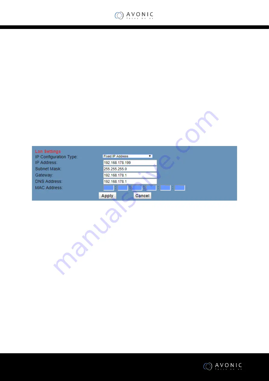
Page 46: ...www avonic eu 46 Network Setting Lan Settings ...

Page 47: ...hen port mapping need to be consistent with the port number default port 80 RTSP Port IP camera support RTSP protocol use the VLC tools broadcast PTZ Port Support PTZ protocol default port 5678 Control Protocol Setting Setting camera control communication protocol include Visca address Pelco D address Pelco P address RTMP Setting Setting the camera stream can set up two stream in the two stream se...

Page 48: ...ecessary to let the changes take effect Go to the System menu and press Reboot button RTSP stream media player rtsp ip port number 1 First stream rtsp ip port number 2 Second stream RTSP port number default 554 IP Port parameters HTTP Port range 80 1024 65535 default 80 RTSP Port range 554 1024 65535 default 554 PTZ Port range 1024 65535 default 5678 Multicast Port range 1024 65535 default 6688 De...

Page 49: ...0p 60 max output The OS will recognize the camera as USB Video Capture Device according to UVC 1 0 Support OS Windows XP 2003 VISTA 7 8 and another system Linux Mac OS General software Windows AMCAP VLC Debut Video Capture etc Linux V412 software driver and VLC media player etc Mac OS FaceTime iChat Photo Booth and Debut Video Capture etc ...

Page 50: ...www avonic eu 50 ...

Page 51: ...y clean it with diluted neuter detergent Do not use any type of solvents which may damages the surface Unqualified Application No shooting extreme bright object for a long period of time such as sunlight light sources etc No operating in unstable lighting conditions otherwise image will be flickering No operating close to powerful electromagnetic radiation such as TV or radio transmitters etc Trou...

Page 52: ...g in Unable to access IP Camera by web browser 1 Access to the network with PC can test whether network works in this way to get rid of cable failure network failure caused by PC virus until the PC can be Ping 2 Disconnect IP Camera with network IP Camera and PC are connected according to the proper operations to re set the IP address 3 Check the server s IP address and subnet mask and gateway add...

Page 53: ...r is set correctly Serial communication cannot control the camera 1 Check the camera working mode 2 Check control cable is connected correctly Contact For any questions or suggestions contact the reseller or the local distributor of Avonic Find the local distributor on the website of Avonic For the recent manual or datasheet look at the Avonic website www avonic eu ...

Page 54: ...ress setting IF_Clear Broadcast 88 01 00 01 FF I F Clear CAM_Power On 8x 01 04 00 02 FF Power ON OFF Off 8x 01 04 00 03 FF CAM_Zoom Stop 8x 01 04 07 00 FF Tele Standard 8x 01 04 07 02 FF Wide Standard 8x 01 04 07 03 FF Tele Variable 8x 01 04 07 2p FF p 0 low 7 high Wide Variable 8x 01 04 07 3p FF Direct 8x 01 04 47 0p 0q 0r 0s FF pqrs Zoom Position Command Function Command Package Note ...

Page 55: ...ntax Error z0 60 02 FF Returned when the command format is different or when a command with illegal command parameters is accepted Command Buffer Full z0 60 03 FF Indicates that two sockets are already being used executing two commands and the command could not be accepted when received Command Canceled z0 6y 04 FF y Socket No Returned when a command which is being executed in a socket specified b...

Page 56: ...d socket number is specified Command Not Executable z0 6y 41 FF y Execution command Socket No Inquiry command 0 Returned when a command cannot be executed due to current conditions For example when commands controlling the focus manually are received during auto focus VISCA Camera Control Command List Command Function Command Package Notes CAM_Focus Stop 8x 01 04 08 00 FF Far Standard 8x 01 04 08 ...

Page 57: ...ZoomFocus Direct 8x 01 04 47 0p 0q 0r 0s pqrs Zoom Position tuvw Focus Position 0t 0u 0v 0w FF CAM_WB Auto 8x 01 04 35 00 FF Normal Auto Indoor mode 8x 01 04 35 01 FF Indoor mode Outdoor mode 8x 01 04 35 02 FF Outdoor mode OnePush mode 8x 01 04 35 03 FF One Push WB mode Manual 8x 01 04 35 05 FF Manual Control mode OnePush trigger 8x 01 04 10 05 FF One Push WB Trigger CAM_RGain Reset 8x 01 04 03 00...

Page 58: ... Manual 8x 01 04 39 03 FF Manual Control mode Shutter priority 8x 01 04 39 0A FF Shutter Priority Automatic Exposure mode Iris priority 8x 01 04 39 0B FF Iris Priority Automatic Exposure mode Bright 8x 01 04 39 0D FF Bright Mode Manual control CAM_SlowShutter AutoSlowShutterLimit 8x 01 04 2A 0p 00 FF CAM_Iris Reset 8x 01 04 0B 00 FF Iris Setting Up 8x 01 04 0B 02 FF Down 8x 01 04 0B 03 FF Direct 8...

Page 59: ...04 0D 02 FF Down 8x 01 04 0D 03 FF Direct 8x 01 04 0D 00 00 0p 0q FF pq Bright Position CAM_ExpComp On 8x 01 04 3E 02 FF Exposure Compensation On Off Off 8x 01 04 3E 03 FF Reset 8x 01 04 0E 00 FF Exposure Compensation Amount Setting Up 8x 01 04 0E 02 FF Down 8x 01 04 0E 03 FF Direct 8x 01 04 4E 00 00 0p 0q FF pq ExpComp Position CAM_BackLight On 8x 01 04 33 02 FF Back Light Compensation On Off Off...

Page 60: ...6 0p FF p Dynamic Hot Pixel Setting 0 0ff level 1 to 6 CAM_ApertureMode sharpness Auto 8x 01 04 05 02 FF Sharpness Auto Manual 8x 01 04 05 02 FF Sharpness Manual CAM_Aperture sharpness Reset 8x 01 04 02 00 FF Aperture Control Up 8x 01 04 02 02 FF Down 8x 01 04 02 03 FF Direct 8x 01 04 42 00 00 0p 0q FF pq Aperture Gain CAM_PictureEffect Off 8x 01 04 63 00 FF Picture Effect Setting B W 8x 01 04 63 ...

Page 61: ... 04 66 03 FF CAM_RegisterValue 8x 01 04 24 mn 0p 0q FF mm Register No 00 7F pp Register Value 00 7F CAM_ColorGain Diret 8x 01 04 49 00 00 00 0p FF p Color Gain setting 0h 60 to Eh 200 SYS_Menu Off 8x 01 06 06 03 FF Turns off the menu screen Pan_tiltDrive Up 8x 01 06 01 VV WW 03 01 FF VV Pan speed 0x01 low speed to 0x18 Down 8x 01 06 01 VV WW 03 02 FF high speed Left 8x 01 06 01 VV WW 01 03 FF WW T...

Page 62: ...n DownLeft 8x 01 06 01 VV WW 01 02 FF DownRight 8x 01 06 01 VV WW 02 02 FF Stop 8x 01 06 01 VV WW 03 03 FF AbsolutePosition 8x 01 06 02 VV WW 0Y 0Y 0Y 0Y 0Z 0Z 0Z 0Z FF RelativePosition 8x 01 06 03 VV WW v0Y 0Y 0Y 0Y 0Z 0Z 0Z 0Z FF Home 8x 01 06 04 FF Reset 8x 01 06 05 FF Pan_tiltLimitSet LimitSet 8x 01 06 07 00 0W 0Y 0Y 0Y 0Y 0Z 0Z W 1 UpRight 0 DownLeft YYYY Pan ...

Page 63: ...y Setting CAM_Brightness Direct 8x 01 04 A1 00 00 0p 0q FF pq Brightness Position CAM_Contrast Direct 8x 01 04 A2 00 00 0p 0q FF pq Contrast Position CAM_Flip Off 8x 01 04 A4 00 FF Flip H 8x 01 04 A4 01 FF Flip V 8x 01 04 A4 02 FF Flip HV 8x 01 04 A4 03 FF Single Command For Video Flip CAM_SettingSave Save 8x 01 04 A5 10 FF Save Current Setting CAM_Iridix Direct 8x 01 04 A7 00 00 0p 0q FF pq Iridi...

Page 64: ...Command Command Package Return Package Note CAM_PowerInq 8x 09 04 00 FF y0 50 02 FF On y0 50 03 FF Off Standby y0 50 04 FF Internal power circuit error CAM_ZoomPosInq 8x 09 04 47 FF y0 50 0p 0q 0r 0s FF pqrs Zoom Position CAM_FocusAFMode Inq 8x 09 04 38 FF y0 50 02 FF Auto Focus y0 50 03 FF Manual Focus CAM_FocusPosInq 8x 09 04 48 FF y0 50 0p 0q 0r 0s FF pqrs Focus Position CAM_WBModeInq 8x 09 04 ...

Page 65: ...er Position CAM_IrisPosInq 8x 09 04 4B FF y0 50 00 00 0p 0q FF pq Iris Position CAM_BrightPosInq 8x 09 04 4D FF y0 50 00 00 0p 0q FF pq Bright Position CAM_ExpCompMod eInq 8x 09 04 3E FF y0 50 02 FF On y0 50 03 FF Off CAM_ExpCompPosI nq 8x 09 04 4E FF y0 50 00 00 0p 0q FF pq ExpComp Position CAM_BacklightMode Inq 8x 09 04 33 FF y0 50 02 FF On y0 50 03 FF Off CAM_Nosise2DMode Ing 8x 09 04 50 FF y0 ...

Page 66: ...reEffectM odeInq 8x 09 04 63 FF y0 50 02 FF Off y0 50 04 FF B W CAM_MemoryInq 8x 09 04 3F FF y0 50 0p FF p Memory number last operated SYS_MenuModeInq 8x 09 06 06 FF y0 50 02 FF On y0 50 03 FF Off CAM_LR_ReverseInq 8x 09 04 61 FF y0 50 02 FF On y0 50 03 FF Off CAM_PictureFlipInq 8x 09 04 66 FF y0 50 02 FF On y0 50 03 FF Off CAM_RegisterValueI nq 8x 09 04 24 mm FF y0 50 0p 0p ff mm Register No 00 t...

Page 67: ... cd Hardware Version mnpq ARM Version rstu FPGA Version vw Camera model 01 C Type 02 M Type 03 S Type VideoSystemInq 8x 09 06 23 FF y0 50 00 FF 1920x1080i60 y0 50 01 FF 1920x1080p30 y0 50 02 FF 1280x720p60 y0 50 04 FF NTSC y0 50 05 FF NTSC y0 50 06 FF NTSC y0 50 07 FF 1920x1080p60 y0 50 08 FF 1920x1080i50 y0 50 09 FF 1920x1080p25 y0 50 0A FF 1280x720p50 y0 50 0C FF PAL ...

Page 68: ...an Position zzzz Tilt Position CAM_TypeInq 8x 09 00 03 FF y0 50 01 FF C Type y0 50 02 FF M Type y0 50 03 FF S Type CAM_DateInq 8x 09 00 04 FF y0 50 0r ss uu uu vv ww 0D FF Version dater Big Version Numberss Little Version Numberuuuu Yearvv Monthww Day CAM_ModeInq 8x 09 04 A6 FF y0 50 00 FF Mode0 y0 50 02 FF Mode2 CAM_GainLimitInq 8x 09 04 2C FF y0 50 0q FF p Gain Limit CAM_DHotPixelInq 8x 09 04 56...

Page 69: ... 09 04 A4 FF y0 50 00 FF Off y0 50 01 FF Flip H y0 50 02 FF Flip V y0 50 03 FF Flip HV CAM_IridixInq 8x 09 04 A7 FF y0 50 00 00 0p 0q FF pq Iridix Position CAM_AFZone 8x 09 04 AA FF y0 50 00 FF Top y0 50 01 FF Center y0 50 02 FF Bottom CAM_ColorHueInq 8x 09 04 4F FF y0 50 00 00 00 0p FF p Color Hue setting 0h 14 dgrees to Eh 14 degrees CAM_AWBSensitivit yInq 8x 09 04 A9 FF y0 50 00 FF High y0 50 0...

Page 70: ...kInq 8x 09 7E 7E 01 FF y0 50 0p 0p 0q 0q 0r 0s tt 0u vv ww 00 xx 0z FF pp R_Gain qq B_Gain r WB Mode s Aperture tt AE Mode uu BackLight uu Exp Comp vv Shutter Position ww Iris Position xx Bright Position z Exp Comp Position CAM_OtherBlockInq 8x 09 7E 7E 02 FF y0 50 0p 0q 00 0r 00 00 00 00 00 00 00 00 00 FF p bit0 Power 1 On 0 Off q bit2 LR Reverse 1 On 0 Off r bit3 0 Picture Effect Mode ...

Page 71: ...0 00 00 00 00 00 00 00 0p 0q rr 0s 0t 0u FF p AF sensitivity q bit0 Picture flip 1 On 0 Off rr bit6 3 Color Gain 0h 60 to Eh 200 s Flip 0 Off 1 Flip H 2 Flip V 3 Flip HV t bit2 0 NR2D level u Gain limit Remark 1 x in the above list refer to the camera address y x 8 ...

Page 72: ...ocus Near 0xFF Address 0x01 0x00 0x00 0x00 SUM Set Preset 0xFF Address 0x00 0x03 0x00 Preset ID SUM Clear Preset 0xFF Address 0x00 0x05 0x00 Preset ID SUM Call Preset 0xFF Address 0x00 0x07 0x00 Preset ID SUM Auto Focus 0xFF Address 0x00 0x2B 0x00 0x01 SUM Manual Focus 0xFF Address 0x00 0x2B 0x00 0x02 SUM Query Pan Position 0xFF Address 0x00 0x51 0x00 0x00 SUM Query Pan Position Response 0xFF Addr...

Page 73: ...xAF XOR Right 0xA0 Address 0x00 0x02 Pan Speed Tilt Speed 0xAF XOR Zoom In 0xA0 Address 0x00 0x20 0x00 0x00 0xAF XOR Zoom Out 0xA0 Address 0x00 0x40 0x00 0x00 0xAF XOR Focus Far 0xA0 Address 0x00 0x80 0x00 0x00 0xAF XOR Focus Near 0xA0 Address 0x01 0x00 0x00 0x00 0xAF XOR Set Preset 0xA0 Address 0x00 0x03 0x00 Preset ID 0xAF XOR Clear Preset 0xA0 Address 0x00 0x05 0x00 Preset ID 0xAF XOR Call Pres...

Page 74: ...AF XOR VISCA over IP commands The Avonic CM6x IP camera is implemented with a TCP server The TCP port number is 5678 by default and can be altered in the WebGUI Once the connection between client and server is set up the client will be able to send PTZ commands to the server The server then parses and executes the PTZ command The Avonic IP Camera has also implemented a UDP server The UDP port numb...

Page 75: ...changed in the WebGUI As all cameras are uniquely identified by their IP address all VISCA addresses of the cameras that are controlled over IP do not necessarily have to be unique Default settings TCP port 5678 UDP port 1259 VISCA address 1 The commands are as follow 1 Camera return commands x Camera Address y Socket Number z Camera Address 8 All parameter values are in HEX ...

Page 76: ...e command could not be accepted when received Command Canceled 90 6y 04 FF y Socket No Returned when a command which is being executed in a socket specified by the cancel command is canceled The completion message for the command is not returned No Socket 90 6y 05 FF y Socket No Returned when no command is executed in a socket specified by the cancel command or when an invalid socket number is spe...

Page 77: ... 01 04 35 00 FF Normal Auto Indoor mode 81 01 04 35 01 FF Indoor mode Outdoor mode 81 01 04 35 02 FF Outdoor mode OnePush mode 81 01 04 35 03 FF One Push WB mode Manual 81 01 04 35 05 FF Manual Control mode OnePush trigger 81 01 04 10 05 FF One Push WB Trigger CAM_RGain Reset 81 01 04 03 00 FF Manual Control of R Gain Up 81 01 04 03 02 FF Down 81 01 04 03 03 FF Direct 81 01 04 43 00 00 0p 0q FF pq...

Page 78: ...1 04 50 02 FF ND2D Auto Manual Manual 81 01 04 50 03 FF CAM_NR 2D Level 81 01 04 53 0p FF p NR Setting 0 Off level 1 to 5 CAM_NR 3D Level 81 01 04 54 0p FF p NR Setting 0 Off level 1 to 8 CAM_Flicker 81 01 04 23 0p FF p Flicker Settings 0 Off 1 50Hz 2 60Hz CAM_DHotPixel 81 01 04 56 0p FF p Dynamic Hot Pixel Setting 0 0ff level 1 to 6 CAM_ApertureMod e sharpness Auto 81 01 04 05 02 FF Sharpness Aut...

Page 79: ...06 02 VV WW 0Y 0Y 0Y 0Y 0Z 0Z 0Z 0Z FF RelativePosition 81 01 06 03 VV WW 0Y 0Y 0Y 0Y 0Z 0Z 0Z 0Z FF Home 81 01 06 04 FF Reset 81 01 06 05 FF Pan_tiltLimitSet LimitSet 81 01 06 07 00 0W 0Y 0Y 0Y 0Y 0Z 0Z 0Z 0Z FF W 1 UpRight 0 DownLeft YYYY Pan Limit Position ZZZZ Tilt Position LimitClear 81 01 06 07 01 0W 07 0F 0F 0F 07 0F 0F 0F FF CAM_AFSensitivity High 81 01 04 58 01 FF AF Sensitivity High Norm...

Page 80: ...d Packet Packet Comments CAM_ZoomPosInq 81 09 04 47 FF 90 50 0p 0q 0r 0s FF pqrs Zoom Position CAM_FocusAFMod eInq 81 09 04 38 FF 90 50 02 FF Auto Focus 90 50 03 FF Manual Focus CAM_FocusPosInq 81 09 04 48 FF 90 50 0p 0q 0r 0s FF pqrs Focus Position CAM_WBModeInq 81 09 04 35 FF 90 50 00 FF Auto 90 50 01 FF Indoor mode 90 50 02 FF Outdoor mode 90 50 03 FF OnePush mode 90 50 05 FF Manual CAM_RGainIn...

Page 81: ... 1 50Hz 2 60Hz CAM_ApertureMod eInq Sharpness 81 09 04 05 FF 90 50 02 FF Auto Sharpness 90 50 03 FF Manual Sharpness CAM_ApertureInq Sharpness 81 09 04 42 FF 90 50 00 00 0p 0q FF pq Aperture Gain CAM_PictureEffect ModeInq 81 09 04 63 FF 90 50 02 FF Off 90 50 04 FF B W CAM_MemoryInq 81 09 04 3F FF 90 50 0p FF p Memory number last operated SYS_MenuModeIn q 81 09 06 06 FF 90 50 02 FF On 90 50 03 FF O...

Page 82: ...0 01 FF High 90 50 02 FF Normal 90 50 03 FF Low CAM_BrightnessIn q 81 09 04 A1 FF 90 50 00 00 0p 0q FF pq Brightness Position CAM_ContrastInq 81 09 04 A2 FF 90 50 00 00 0p 0q FF pq Contrast Position CAM_FlipInq 81 09 04 A4 FF 90 50 00 FF Off 90 50 01 FF Flip H 90 50 02 FF Flip V 90 50 03 FF Flip HV CAM_IridixInq 81 09 04 A7 FF 90 50 00 00 0p 0q FF pq Iridix Position CAM_AFZone 81 09 04 AA FF 90 50...

Page 83: ...camera Use a flat screw driver Step3 Press the Switch ON OFF button on the rear of the camera the power lamp light Step4 Pan Tilt will rotate to the maximum position of top right after the camera started then it return to the center the process of initialization is finished Note If the position preset 0 has been stored the position preset 0 will be called up after initialization ...

Page 84: ...www avonic eu 84 Appendix C Dimensions All sizes are in mm Weight 2 4 kg ...

Reviews: