background image


Page 16 


8  Connect to Webserver 

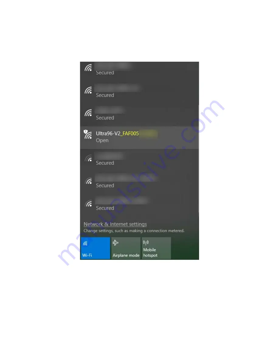
1.  From your Wi-Fi capable host machine, show the available Wi-Fi networks. You should see an 

Open network called Ultra96-V2_<MAC_ADDRESS> as shown below. Note that the MAC Address 
shown will be different than the image below as it will match your specific board’s MAC Address. 


Figure 8 – Ultra96-V2 As An Available Network 


2.  Select the Ultra96-V2 Network and Connect. 


Summary of Contents for AES-ULTRA96-V2-G

Page 1: ...20 Avnet Inc AVNET Reach Further and the Avnet logo are registered trademarks of Avnet Inc All other brands are the property of their respective owners LIT Ultra96 V2 GSG v2 0 Ultra96 V2 Getting Started Guide Version 2 0 ...

Page 2: ...r Version History Version Date Comment 1 0 25 Jun 2019 Initial Ultra96 V2 Getting Started Guide 30 May 2019 image 1 1 01 Oct 2019 Updated based on 17 Sep 2019 image 2 0 18 Dec 2020 Update to the 2020 1 out of box image 23 Nov 2020 image Added PMIC read and program instructions ...

Page 3: ...nect to Webserver 16 9 Ultra96 V2 GPIO LEDs Example Project 18 10 Tutorials 20 11 Access Ultra96 V2 Linux Terminal over SSH 21 12 Connect to External Wi Fi 24 13 Reading On board Telemetry 27 14 PMIC Version Check and Update 31 14 1 PMIC Version Checking 31 14 2 PMIC Reprogramming 35 15 Power Off 37 16 Getting Help and Support 38 16 1 Avnet Support 38 16 2 Xilinx Support 39 17 Installing and Licen...

Page 4: ... 13 Ultra96 V2 Tutorials 20 Figure 14 TeraTerm New Connection 21 Figure 15 SSH Terminal Settings 22 Figure 16 Click Continue 22 Figure 17 SSH Authentication 23 Figure 18 Ultra96 V2 Terminal 23 Figure 19 WiFi Setup 24 Figure 20 Discovering Networks 24 Figure 21 Successfully Connected 25 Figure 22 Determine IP Address Assigned to Ultra96 V2 25 Figure 23 Connected to Ultra96 V2 Via External Wi Fi 26 ...

Page 5: ... 0x13 or 0x14 34 Figure 35 Compare PMIC Config to a File 0x15 34 Figure 36 Carefully Read then Confirm to Proceed 35 Figure 37 Programming 0x13 Succeeded 35 Figure 38 Power Down Initiated Through Short Press of SW4 37 Figure 39 Voucher Confirmation 41 Figure 40 Generate Node Locked 41 Figure 41 Select Host Information 42 ...

Page 6: ...Scale MPSoC Designers can create or evaluate designs for both the Zynq Processor Subsystem PS and the Programmable Logic PL fabric Figure 1 Ultra96 V2 This Getting Started Guide will outline the steps to setup the Ultra96 V2 hardware It documents the procedure to run a Linux design running on the Quad core ARM Cortex A53 MPCore Processing System PS ...

Page 7: ...ards Click Mezzanine for adding Click boards to the Ultra96 V2 o Mezzanine only AES ACC U96 ME MEZ o Starter kit including 3 Click boards AES ACC U96 ME SK o http avnet me ClickMezzanine o Additional Click boards available at http avnet me Click 96Boards Dual Camera Mezzanine for adding image sensors to the Ultra96 V2 o AES ACC U96 ONCAM MEZ o http avnet me DualCameraMezz 96Boards Quad Ethernet Me...

Page 8: ...Started Guide Hardware User Guide Schematics Bill of Materials Mechanical drawing 3D Model Programmable logic PL master user constraints Board definition files for Vivado integration available at https github com Avnet bdf 3 2 Tutorials and Reference Designs https www hackster io avnet products ultra96 v2 3 3 Trainings and Videos Live and On Demand Technical Training Courses at http avnet me TTC ...

Page 9: ...cy power management Mini DisplayPort MiniDP or mDP 1x USB 3 0 Type Micro B upstream port 2x USB 3 0 Type A downstream ports 1x USB 2 0 Type A downstream port on High speed expansion header 40 pin Low speed expansion header 60 pin High speed expansion header Thermally dissipative device o Rev 1 datecodes 1935 and earlier Mounted on thermal bracket with fan o Rev 1 datecodes 1936 and later Custom Aa...

Page 10: ...Page 10 Figure 2 Ultra96 V2 Block Diagram ...

Page 11: ... circuits through PetaLinux including SSH Terminal Access GPIO LEDs Wi Fi In addition to the items included in the kit you will also need the following to complete the exercises in this tutorial Ultra96 USB to JTAG UART Pod required for terminal access or Monitor requires connection to miniDP port keyboard mouse An Ultra96 V2 image in its expected out of box configuration is shown below along with...

Page 12: ...ge to your 16GB card 3 Insert the microSD card into the Ultra96 V2 card cage J2 7 Run the Out of Box Design 1 A terminal program is recommended if you want to view terminal output TeraTerm was used in this example which can be downloaded from the TeraTerm project on the SourceForge Japan page ttssh2 sourceforge jp Install TeraTerm or another terminal program of your choice 2 Set the Ultra96 V2 boo...

Page 13: ...a96 V2 is compatible with Pods that have 3 pin and 7 pin receptacles align as seen in Figure 5 below as well as Pods with 4 pin and 8 pin receptacles as seen in Figure 6 below You can find more information about the JTAG UART pod here http avnet me JTAG UART pod vref Figure 5 Ultra96 V2 with older 3 pin JTAG UART Pod This Pin Not Connected is OK ...

Page 14: ...ort cable with DisplayPort Monitor ACTIVE mini DP to HDMI adapter cable with HDMI Monitor 5 Plug in your 12V Barrel Jack power supply into a wall outlet and then connect the barrel jack to J10 on your Ultra96 V2 Green Vin status LED D17 will light but the board is not yet powered on Note DC power supply is not included in the Ultra96 V2 kit but can be purchased separately http avnet me 96boardpowe...

Page 15: ...stall the driver for the FT2232H device Visit www ftdichip com Drivers VCP htm then download and install the appropriate driver for your operating system Launch your Serial Terminal with settings of 115200 8 N 1 7 Press and release the power button SW4 Figure 7 Press the SW4 Power On Button 8 The Green Power On LED D2 Red INIT_B LED D5 and the Green User LEDs should illuminate After a few seconds ...

Page 16: ... networks You should see an Open network called Ultra96 V2_ MAC_ADDRESS as shown below Note that the MAC Address shown will be different than the image below as it will match your specific board s MAC Address Figure 8 Ultra96 V2 As An Available Network 2 Select the Ultra96 V2 Network and Connect ...

Page 17: ...7 3 Once connected open a browser on the connected machine and browse to the IP address of the board which is http 192 168 2 1 The browser page will show like below Figure 9 Connected to Ultra96 V2 Webserver ...

Page 18: ...e Ultra96 V2 LEDs are D3 D4 D6 and D7 shown below Figure 10 Ultra96 V2 User LEDs 1 Next we want to access the Ultra96 V2 GPIO LEDs example project From the Ultra96 V2 home page select Ultra96 V2 GPIO LEDs example project Figure 11 Ultra96 V2 GPIO LEDs ...

Page 19: ...menus and begin changing the status of the GPIO LEDs The LED blinking upon boot up is D3 so consider changing that one first to On Figure 12 LED0 D3 Changed to Steady state ON 3 Scroll to the bottom of the webpage and you will see a definition table for various LED selection options ...

Page 20: ...V2 As of now we have interacted using the Webserver and UART on the Pod 5 To explore your Ultra96 V2 over miniDP you will need a compatible cable and monitor For example the following combinations work miniDP to DP cable with DisplayPort Monitor Active miniDP to HDMI cable with HDMI Monitor 6 Read through the SSH section it states we can access the Ultra96 V2 terminal using TeraTerm or a PuTTY ter...

Page 21: ...21 11 Access Ultra96 V2 Linux Terminal over SSH 1 If connected via UART click File Disconnect 2 Open TeraTerm and then select File New connection as seen in the image below Figure 14 TeraTerm New Connection ...

Page 22: ...SSH select TCP IP and then configure your Terminal settings to use the IP address that you discovered previously similar to the below figure Figure 15 SSH Terminal Settings 4 Select OK 5 If you get a SECURITY WARNING click Continue to add this machine to the known hosts list Figure 16 Click Continue ...

Page 23: ...s looking for the Linux terminal s user name and passphrase which are root and root Please type in root for the User name and then type in root for the Passphrase as well Then select OK Figure 17 SSH Authentication 7 You now have access to the Ultra96 V2 Terminal Figure 18 Ultra96 V2 Terminal ...

Page 24: ...ick Configurations and then WiFi Setup Figure 19 WiFi Setup 2 Click the Refresh Connections button then click the pull down for Network Name Next select a network available to you Figure 20 Discovering Networks 3 If a passphrase is required first select the radio button for Text Field Enter the Network Passphrase into the Network Passphrase box then click Connect ...

Page 25: ...e external Wi Fi router You can do this by logging into the router or you can use the terminal from the JTAG UART Pod as shown below 4 In the terminal enter command ifconfig to determine the assigned IP address Figure 22 Determine IP Address Assigned to Ultra96 V2 5 Connect your host to the same Wi Fi source With both your host and Ultra96 V2 board connected to the same Wi Fi source point your bro...

Page 26: ...Page 26 Figure 23 Connected to Ultra96 V2 Via External Wi Fi ...

Page 27: ...u can also view a more advanced project related to this on Hackster https www hackster io AlbertaBeef monitoring power on the avnet platforms e52a23 For now we will show the simple method of reading back the telemetry 1 Connect to the Linux Terminal either through SSH or the UART To see the available I2C busses available type in your console i2cdetect l Figure 24 I2Cdetect This shows all the avail...

Page 28: ...ter Y to confirm The addresses associated with the PMICs are shown below Figure 26 PMICs on I2C 6 3 Read the telemetry from the PMICs by entering sensors in your terminal The output will scroll to the screen which is copied below in sections Figure 27 Telemetry from PMIC 0x15 45 ...

Page 29: ...Page 29 Figure 28 Telemetry from PMIC 0x13 43 Figure 29 Telemetry from MPSoC Sysmon ...

Page 30: ...Page 30 Figure 30 Telemetry from PMIC 0x14 44 As you can see the current voltage and temperature measurements are reported back ...

Page 31: ...amming locations Each time the devices are reprogrammed another location is consumed Use with caution If you accidentally program a device with the wrong file like the 0x14 device with the 0x13 file or vice versa you WILL damage your board and it will NOT be covered under warranty You must program the correct file to the correct device Permanent damage will occur otherwise 14 1 PMIC Version Checki...

Page 32: ... pmic_prog write 6 0x13 0x069e 0x7F to write 0x7F at address 0x069e loop A ot_fault_limit for IRPS5401 of chip 0x13 on i2c bus 6 read registers I2C_BUS CHIP_ADDR o OUTPUT_FILE i INPUT_FILE to read all the registers with I2C_BUS the i2c bus number decimal 0 255 CHIP_ADDR the chip address hex 0x00 0xFF o OUTPUT_FILE Save the register values in the OUTPUT_FILE file optional i INPUT_FILE Check the reg...

Page 33: ... Rocky 5401 devices 0x13 and 0x14 a date code is stored at locations 0x2A and 0x2B for each PMIC You can see which revision you have by reading these two registers 0x2A has the day and 0x2B has the month of release pmic_prog read 6 0x13 0x002A pmic_prog read 6 0x13 0x002B pmic_prog read 6 0x14 0x002A pmic_prog read 6 0x14 0x002B Figure 33 Example datecode October 30 for Device 0x13 ...

Page 34: ...30 txt pmic_prog read registers 6 0x14 i pmic configs U96V2_5401_0x14_191030 txt pmic_prog read registers 6 0x15 i pmic configs U96V2_38060_0x15_190301 txt Figure 34 Compare PMIC Config to a File 0x13 or 0x14 Since the Manhattan 38060 does not store a date code in the config look specifically at the number of differences to see if your programming matches Figure 35 Compare PMIC Config to a File 0x...

Page 35: ...overed under warranty You must program the correct file to the correct device Permanent damage will occur otherwise 1 To reprogram the 0x13 device enter the following command making sure that the two highlighted numbers match pmic_prog program 6 0x13 i pmic configs U96V2_5401_0x13_191030 txt 2 Enter y to confirm 3 A second warning requires you to confirm again This also tells you how many of the U...

Page 36: ...xt 6 Follow the procedure as before The 0x15 Manhattan 38060 device programming has not been updated since the original release of the board Therefore this one does not need to be reprogrammed 7 You should now power cycle the board Enter the poweroff command After the board has fully shut down no LEDs other than Input Power then turn the board back on by pressing the ON switch SW4 ...

Page 37: ...xt to USB port J8 2 You will notice your board does not power down immediately It will take roughly 10 20 seconds for your board to completely power down The reason behind this is it is adhering to the various power down sequencing requirements See the message in the terminal as shown Figure 38 Power Down Initiated Through Short Press of SW4 3 Please note if you do not let your Ultra96 V2 power of...

Page 38: ...o participate in the forums and offer help to others when possible To access Ultra96 V2 collateral please visit the community support page at http avnet me ultra96 v2 To access the latest Ultra96 V2 documentation click on the Technical Documents tab To access the latest reference designs for Ultra96 V2 click on the Reference Designs tab To access the Ultra96 V2 technical forums go to http avnet me...

Page 39: ...al contact support html For technical support including the installation and use of the product license file contact Xilinx Online Technical Support at www xilinx com support The following assistance resources are also available on the website Software IP and documentation updates Access to technical support web tools Searchable answer database with over 4 000 solutions User forums ...

Page 40: ...ided on the Avnet GitHub You must license your Vivado Design Suite Design Edition with the license that came with your Ultra96 V2 To obtain your free license visit the following website and insert the voucher code from the certificate included in your kit http www xilinx com getlicense 1 Log in 2 Fill out information at Product Licensing Name and Address Verification then click Next 3 Select your ...

Page 41: ...screen click Yes Figure 39 Voucher Confirmation 6 Under Certificate Based Licenses find OEM Zynq ZU3 Ultra96 Vivado Design Edition Voucher pack and check the box Now click Generate Node Locked License Figure 40 Generate Node Locked ...

Page 42: ...Page 42 7 Create or select your Host ID Click Next Figure 41 Select Host Information ...

Page 43: ...been installed then no further software will be needed Please check online for any updates at www xilinx com support download index htm For detailed instructions on installing and licensing the Xilinx tools please refer to the latest version of Vivado Design Suite User Guide Release Notes Installation and Licensing UG973 ...

Page 44: ...led lab environment by professional developers for prototype and development purposes only The board included in the kit is not intended for production use unless additional end product testing and certification is performed 19 Safety Warnings This product shall only be connected to an external power supply that is 96boards compliant Only compatible plug in modules shall be connected to Ultra96 V2...

Reviews: