AVK 820 SERIES Installation & Maintenance Instructions Manual Download Page 1

1. INTRODUCTION

To guarantee the benefits of the butterfly valves, proper procedures and  

compliance with this installation instruction are essential. The installation 

must be carried out according to 

good installation practise

 and only by  

qualified personnel. AVK reserves the right to decline responsibility for  

damage or failure caused by non-compliance with the recommendations  

in this instruction. 

Please note that fluid residues inside the butterfly valve may be dangerous to 

people and to the environment. The butterfly valve must be handled with the 

necessary precaution and must be carefully cleaned prior to maintenance. 

Any kind of maintenance is performed on the user´s own risk and must be 

executed by trained staff only. Only original spare parts must be used.

Dimensions, materials and application of the butterfly valves are according to 

series 820 datasheets.
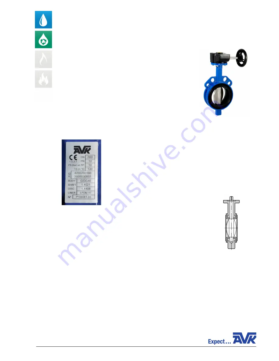
2. MARKING

Label:

•  Manufacturer

•  Product specification

•  Item number

•  Material specification

•  Internal order number 

3. STORAGE

AVK butterfly valves must always be stored free from dust and humidity.

The valve is supplied with the disc slightly open and must remain so until the installation is 

completed (fig. 1).

Butterfly valves supplied with a single acting spring closing pneumatic actuator must be 

stored with disassembled actuator to avoid a permanent deformation of the liner. The  

actuator is mounted after installation of the valve in the piping.

INSTALLATION & MAINTENANCE INSTRUCTIONS - ORIGINAL VERSION

AVK BUTTERFLY VALVES, CENTRIC WITH LOOSE LINER 

SERIES 820

COPYRIGHT©AVK GROUP A/S 2014 - AVK INTERNATIONAL A/S, BIZONVEJ 1, DK-8464 GALTEN - WWW.AVKVALVES.EU 


MI Butterfly820 rev. C August 2017 GB

FIG. 1

Summary of Contents for 820 SERIES

Page 1: ... Only original spare parts must be used Dimensions materials and application of the butterfly valves are according to series 820 datasheets 2 MARKING Label Manufacturer Product specification Item number Material specification Internal order number 3 STORAGE AVK butterfly valves must always be stored free from dust and humidity The valve is supplied with the disc slightly open and must remain so un...

Page 2: ...en standard DIN PN10 16 or ANSI150 flanges For installation of valves between flanges of other standards please consult AVK or its authorised distributors The valve should not be mounted directly in pipes where the actual bore dimension is smaller than the nominal bore dimension of the valve In such cases spacer rings should be fitted between flanges and valve to prevent damage to the disc when op...

Page 3: ...nd Dmax Dmin Minimum diameter of the flange enabling move of the disc in case of a perfectly centered valve Dopt Diameter of the flange for optimal mounting Dmax Maximum diameter of the flange DN 32 40 50 65 80 100 125 150 200 250 300 350 400 450 500 600 700 800 900 1000 1200 1400 1600 Dmin 19 32 35 53 74 93 119 147 198 247 297 340 384 425 490 585 680 790 880 980 1175 1348 1560 Dopt 34 42 53 68 83...

Page 4: ...40 8 M24x60 16 M27x260 8 M27x 70 500 127 16 M24x260 8 M24x60 16 M30x290 8 M30x 80 600 154 16 M27x300 8 M27x70 16 M33x330 8 M33x 90 700 165 20 M27x320 8 M27x80 20 M33x340 8 M33x 90 800 190 20 M30x360 8 M30x80 20 M36x380 8 M36x100 900 203 24 M30x370 8 M30x80 24 M36x410 8 M36x100 1000 216 24 M33x400 8 M33x90 24 M39x450 8 M39x120 1200 254 28 M36x470 8 M36x110 28 M45x550 8 M45x150 1400 280 32 M39x530 8...

Page 5: ... 14033 1200 F30 100 round key 10024 12029 14216 17132 1400 F30 120 round key 12575 18225 27724 1600 F35 130 round key 16767 24239 44834 13 KV VALUES M3 H Opening angle of the valve DN 20 30 40 50 60 70 80 90 32 1 5 5 10 15 26 34 40 40 2 7 8 5 16 25 37 46 50 50 2 7 15 28 45 68 88 100 65 3 11 24 48 85 138 180 210 80 8 22 50 83 134 230 312 360 100 15 35 70 130 225 410 585 650 125 28 70 135 230 360 60...

Page 6: ...lower part opposite the top of the valve Make sure the liner is not damaged 4 5 Insert the shaft through the liner and disc by rotating the disc in an alternate movement to ease the operation 4 6 The axis of the shaft square must be properly aligned with the axis of the disc Then completely insert the shaft by evacuating air from the lower shaft housing slightly lift the liner using a screwdriver ...

Reviews: