Installation Guide
Avigilon H5A Corner Camera Models:
3.0C-H5A-CR1-IR
3.0C-H5A-CR1-IR-SS
5.0C-H5A-CR1-IR
5.0C-H5A-CR1-IR-SS
Page 1: ...Installation Guide Avigilon H5A Corner Camera Models 3 0C H5A CR1 IR 3 0C H5A CR1 IR SS 5 0C H5A CR1 IR 5 0C H5A CR1 IR SS ...
Page 2: ...t or other intellectual property rights of Avigilon Corporation or its licensors Disclaimer This document has been compiled and published using product descriptions and specifications available at the time of publication The contents of this document and the specifications of the products discussed herein are subject to change without notice Avigilon Corporation reserves the right to make any such...
Page 3: ...over Ethernet PoE 13 W min l Do not connect directly to mains power for any reason CAUTION Failure to observe the following instructions may result in injury to persons or damage to the device l Do not expose the camera directly to high levels of x ray laser or UV radiation Direct exposure may cause permanent damage to the image sensor l Do not install near any heat sources such as radiators heat ...
Page 4: ...an outlet on a circuit different from that to which the receiver is connected l Consult the dealer or an experienced radio TV technician for help Changes or modifications made to this equipment not expressly approved by Avigilon Corporation or parties authorized by Avigilon Corporation could void the user s authority to operate this equipment Disposal and Recycling Information When this product ha...
Page 5: ...Corner Camera Base 13 Connecting Cables 17 Mounting the Camera Gimbal to the Base 17 Installing the Front Cover 18 Initializing a Camera Username and Password 19 Optional Using the USB Wi Fi Adapter 20 Assigning an IP Address 21 Accessing the Live Video Stream 21 Optional Configuring microSD Card Storage 21 Zooming and Focusing the Camera 21 Configuring the Camera 22 Cable Connections 23 Connectin...
Page 6: ...Cleaning 30 Dome Bubble 30 Body 30 For More Information 31 Limited Warranty and Technical Support 32 vi ...
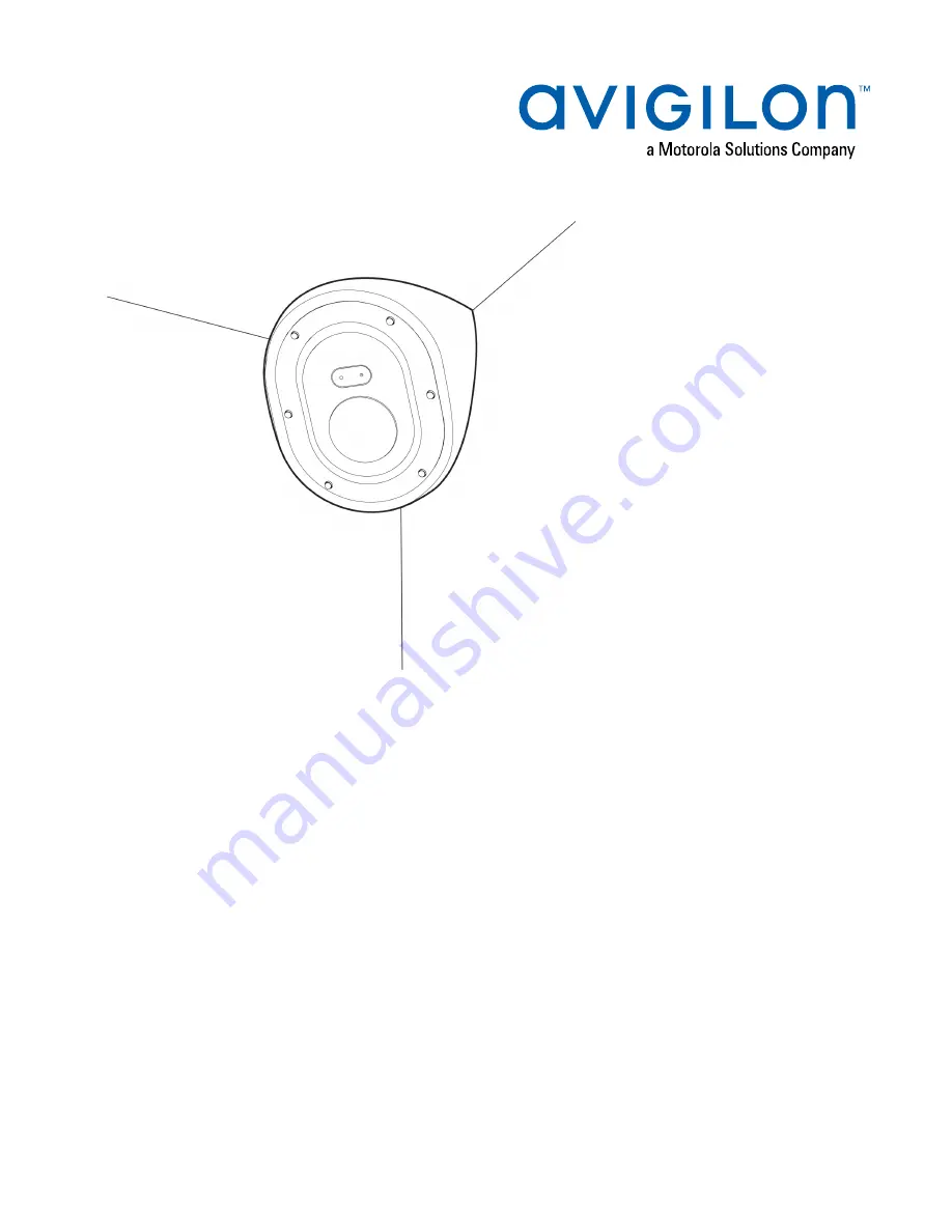
Page 7: ...rding LED LED turns on when the camera is streaming video to a local microSD card ACC or another VMS system or the camera web interface 3 Microphone Built in audio receiver 4 Tamper resistant screws Tamper resistant captive screws to fix the dome cover to the base Overview 1 ...
Page 8: ...ver to power the Recording LED and IR LED 3 Microphone cable Connect the cable to the microphone audio connector on the front cover to use the build in microphone 4 Tilt lock thumb screw Provides a locking mechanism for the image tilt adjustment 5 Lanyard hook A hook for connecting the lanyard on the camera cover Housing Front View 2 ...
Page 9: ...Accepts a microSD card for onboard storage For more information see Optional Configuring microSD Card Storage on page 21 2 Audio microphone cable connector The audio microphone cable comes pre installed to this connector GimbalSide View 3 ...
Page 10: ... Power connector block Accepts a terminal block with either an AC or DC power connection DC input can be either polarity Only required when Power over Ethernet is not available 3 Connection status LED indicator Green LED provides information about device operation For more information see Connection Status LED Indicator on page 26 4 Link LED indicator Amber LED indicates if there is an active conn...
Page 11: ...ont View 1 Micro USB port Accepts a micro USB to USB adapter Only required when using the Avigilon USB Wi Fi Adapter 2 I O connector block Provides connections to external input output devices GimbalFront View 5 ...
Page 12: ...Housing Rear View 1 Cable entry holes x2 Entry holes for the cables required for camera operation 2 Mounting holes Mounting points for the camera x6 with rubber grommets inserted Housing Rear View 6 ...
Page 13: ...s to the lanyard anchor on the camera base 2 Microphone connector Connect the microphone audio cable to use the built in microphone 3 LED connector Connect the LED cable to power the camera s Recording LED and IR LED Cover Rear View 7 ...
Page 14: ...g mounting holes in the mounting surface l Cutting tool for cutting cable access hole in the mounting surface l Silicone sealant Camera Package Contents Ensure the package contains the following l Avigilon H5A Corner camera l RJ 45 grommet piercing cap l Microphone audio cable l 2 cable entry grommets l 6 wall anchors for solid walls for 8 10 screws l 6 mounting screws 10 1 25 long flat head Phill...
Page 15: ...e housing Note Be careful not to scratch or touch the dome bubble The resulting marks or fingerprints may affect the overall image quality Keep the protective covers on the outside of the dome bubble until the installation is complete 1 Loosen the screws that fix the cover to the base Use the supplied driver to loosen the screws 2 Pull the front cover off of the camera base Installation Steps 9 ...
Page 16: ...at secure the gimbal to the base 4 Rotate the bottom part of the gimbal upwards after the screws are removed A then unhook the gimbal from the slot at the top of the housing and pull the gimbal out B Removing the Front Cover and Gimbal 10 ...
Page 17: ...x configuration cable that comes pre installed on the camera Preparing the Mounting Grommets There are 6 mounting holes in the camera housing Each mounting hole is filled by a grommet to help Preparing the Mounting Grommets 11 ...
Page 18: ...d aiming recommendations to maximize the camera s analytics capabilities l The camera should be installed above 274 cm 9 l The camera should tilt downwards no more than 45 degrees l The camera image should be level with the horizon line l The camera should be mounted to a stable surface to minimize the physical movement of the camera after installation For more details see Designing a Site for Vid...
Page 19: ...ches the one shown in the image 3 Push any other required cables through the second grommet Note If you will pull multiple cables through the sealing grommet apply silicone sealant to seal any gaps in the grommet Mounting the Corner Camera Base Perform the following steps to mount the camera base 1 Place the base into the mounting location Make sure that the mounting grommet pins have been removed...
Page 20: ...sure the camera is mounted securely and to make the camera ligature proof 3 Remove the base from the mounting surface Drill the 6 mounting holes and one cable entry hole into the mounting surface 4 Insert the wall anchors into the mounting holes Mounting the Corner Camera Base 14 ...
Page 21: ...red cables pulled through into the cable entry holes on the back of the camera base For more information see Inserting Cables through the Sealing Grommet on page 12 7 Place the camera base in the mounting location and drive the 6 mounting screws to secure it in place Mounting the Corner Camera Base 15 ...
Page 22: ...8 Apply silicone sealant around the edges of the camera base to prevent moisture from entering the mounting surface Mounting the Corner Camera Base 16 ...
Page 23: ...Connect power using one of the following methods o Power over Ethernet PoE Class 3 If PoE is available the LEDs will turn on o External Power Connect an external 12 V DC or 24 V AC power source to the power connector block 5 Check that the Connection Status LED indicator indicates the correct state For more information see Connection Status LED Indicator on page 26 Mounting the Camera Gimbal to th...
Page 24: ...ect to the camera and adjust the aim zoom and focus so that the camera covers the required field of view For more information see l Assigning an IP Address on page 21 l Mounting the Camera Gimbal to the Base on the previous page l Configuring the Camera on page 22 Be careful not to touch or scratch the dome bubble Any marks or fingerprints on the dome bubble will cause unwanted reflections Install...
Page 25: ...hone audio cable to the connector on the front cover B 4 Fit the front cover into place C 5 Secure the front cover to the camera base by tightening the 6 screws with the supplied driver Initializing a Camera Username and Password Cameras manufactured after January 1 2020 do not have a default username or password and will be in a factory default state Initializing a Camera Username and Password 19...
Page 26: ... later when connecting a camera in the factory default state the client software will ask you to create a new user For more information see the Avigilon Control Center Client User Guide l Avigilon Cloud Services ACS v3 0 or later when adding a camera you will be asked to create a new user for cameras in the factory default state For more information see the Avigilon Cloud Services User Guide Tip I...
Page 27: ... IP address l Network video management software application for example the Avigilon Control Center software Optional Configuring microSD Card Storage To use the camera s SD card storage feature you must insert a microSD card into the card slot It is recommended that the microSD card have a write speed of class 10 or better If the microSD card does not meet the recommended write speed the recordin...
Page 28: ...see Avigilon USB Wi Fi Adapter System User Guide l If you have installed multiple cameras you can use the Avigilon Camera Configuration Tool to configure common settings For more information see the Avigilon Camera Configuration Tool User Guide l If the camera is connected to the Avigilon Control Center system you can use the client software to configure the camera For more information see the Avi...
Page 29: ... not nick or damage the wires 3 Insert the two power wires into the two terminals on the power connector block The connection can be made with either polarity Use a small slotted 5 64 or 2 mm blade width screwdriver to loosen and tighten the terminals 4 Attach the power connector block back into the camera WARNING This product is intended to be supplied by a UL Listed Power Unit marked Class 2 or ...
Page 30: ...nput to the Ground pin To deactivate leave disconnected or apply between 3 15 V 3 Output When active Output is internally connected with the Ground pin Circuit is open when inactive Maximum load is 25 VDC 120 mA Connecting to ExternalDevices 24 ...
Page 31: ...l Relay l Switch Connecting to ExternalDevices 25 ...
Page 32: ... the camera s web user interface For more information see the Avigilon High Definition H4 and H5 IP Camera Web Interface User Guide Troubleshooting Network Connections and LED Behavior Note For any of the below LED behaviors ensure that the camera is getting power and is using a good network cable before trying another solution LED Behavior Suggested Solution l Green LED is off and amber is on Per...
Page 33: ... firmware revert button Resetting through the camera s web interface will not produce the desired result l A different LED blinking pattern than those described above Perform a factory reset of the camera using the physical firmware revert button Resetting through the camera s web interface will not produce the desired result Troubleshooting NetworkConnections and LEDBehavior 27 ...
Page 34: ...the following diagram For models that feature an SD card slot resetting the camera will not affect video that has been recorded to the SD card 1 Ensure the device is powered on 2 Using a straightened paperclip or similar tool gently press and hold the firmware revert button 3 Release the button after three seconds CAUTION Do not apply excessive force Inserting the tool too far may damage the camer...
Page 35: ...rence 2 Open a Command Prompt window and enter the following commands a arp s New Camera IP Address Camera MAC Address For example arp s 192 168 1 10 00 18 85 12 45 78 b ping l 123 t New Camera IP Address For example ping l 123 t 192 168 1 10 3 Reboot the camera 4 Close the Command prompt window when you see the following message Reply from New Camera IP Address Setting the IP Address Using the AR...
Page 36: ...erprints l Use a microfiber cloth or non abrasive fabric to dry the dome bubble Important Failure to use the recommended cleaning materials may result in a damaged or scratched dome bubble A damaged dome bubble may negatively impact image quality and cause unwanted IR light reflecting into the lens Body l Use a dry or lightly dampened cloth to clean the camera body l Do not use strong or abrasive ...
Page 37: ...lon Control Center Client User Guide l Web Interface User Guide Avigilon High Definition H4 and H5 IP Cameras l Avigilon Camera Configuration Tool User Guide l Designing a Site with Avigilon Video Analytics These guides are available on help avigilon com and on the Avigilon website avigilon com support For More Information 31 ...
Page 38: ...t Avigilon warranty terms for this product are provided at avigilon com warranty Warranty service and technical support can be obtained by contacting Avigilon Technical Support avigilon com contact Limited Warranty and TechnicalSupport 32 ...