background image

10

EnglishEnglish

Connecting to External Devices

External devices are connected through the I/O terminal. The pinout
for the I/O terminal is shown in the following table and diagram.
Consult the software user guide for details on how to configure the
external devices.

Figure: 

External I/O terminal schematics and example application.

 Table:External I/O Terminals

Pin

Function

Description

1

GND

Ground for RS-485 interface.

2

RS-485 RX/TX+

Half-duplex RS-485 interface for controlling 
external equipment

3

RS-485 RX/TX-

4

Input (-)/Output A Shared pin for Input and Output.

5

Input (+)

The input uses a photocoupler and is 
electrically isolated from the internal circuitry. 
The input voltage should not exceed 12 V.

6

Output B

The output uses a photocoupler and is 
electrically isolated from the internal circuitry. 
The output terminal (A and B) connections can 
be made with either polarity. The output can 
drive a maximum load of 50 V and 120 mA. 

RS-485

1

2

3

4

5

6

24V

3V

+

+

-

-

External Device

Relay

Switch

Camera

Summary of Contents for 11MP-HD-PRO-C

Page 1: ...Installation Guide Avigilon High Definition Professional IP Camera Models 29MP HD PRO C 29MP HD PRO M 16MP HD PRO C 16MP HD PRO M 11MP HD PRO C 11MP HD PRO M 8MP HD PRO C and 8MP HD PRO M 920 0002A Rev2 ...

Page 2: ......

Page 3: ...ust be performed by qualified personnel only and must conform to all local codes Use only UL listed mounting bracket suitable for the mounting surface and minimum 1 15 kg 2 5 lb weight plus the weight of the attached lens This product is intended to be supplied by a UL Listed Power Unit marked Class 2 or LPS or Limited Power The Warning symbol indicates the presence of dangerous voltage within and...

Page 4: ...as been damaged such as from a liquid spill or fallen objects has been exposed to rain or moisture does not operate normally or has been dropped Do not use strong or abrasive detergents when cleaning the device body Use only accessories recommended by Avigilon Avoid leaving the image sensor exposed for extended periods of time Always cover the image sensor with either a lens or a dust cap Do not a...

Page 5: ...when the equipment is operated in a commercial environment This equipment generates uses and can radiate radio frequency energy and if not installed and used in accordance with the instruction manual may cause harmful interference to radio communications Operation of this equipment in a residential area is likely to cause harmful interference in which case the user will be required to correct the ...

Page 6: ...aste When this product reaches its end of life take it to a collection point designated by local authorities Some collection points accept products for free The separate collection and recycling of your product at the time of disposal will help conserve natural resources and ensure that it is recycled in a manner that protects human health and the environment ...

Page 7: ... the publication Intellectual Property Notice No license is granted by implication or otherwise under any industrial design industrial design rights patent patent rights or copyrights of Avigilon Corporation or its licensors Trademarks and registered trademarks are the property of their respective owners Portions of the software in this product are licensed under the eCos License Distribution of e...

Page 8: ...ation Steps 3 Mounting the Lens 4 Mounting the Camera 5 Connecting Power 5 Aiming and Focusing the Camera 7 Connecting to the Network Video Recorder 7 IP Address Selection 8 Advanced Features 9 Upgrading the Firmware 9 Connecting to External Devices 10 Cleaning 11 Image Sensor 11 Body 12 Specifications 13 Limited Warranty Technical Support 14 ...

Page 9: ...mission occurs over this connection Also receives power when it is connected to a network that provides Power over Ethernet The Ethernet Port has two status lights indicating link left and activity right Power Connector Block Accepts a terminal block with either AC or DC power connection DC input can be either polarity Only required when Power over Ethernet is not available I O Terminals Provides ...

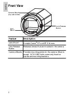
Page 10: ...F and EF S lenses Lens Release Button Releases lenses that are mounted to the camera Camera Mounts Provides mounting points for the camera Mounts accept 1 4 20 UNC bolts commonly found on tripods and mounting brackets Lens Release Button Camera Mounts top and bottom Lens Mount ...

Page 11: ...wer over Ethernet Package Contents Ensure the package contains the following Avigilon High Definition IP Camera Dust Cap Terminal Block Installation Steps Complete the following procedures to install the camera 1 Mounting the Lens on page 4 2 Mounting the Camera on page 5 3 Connecting Power on page 5 4 Aiming and Focusing the Camera on page 7 5 Connecting to the Network Video Recorder on page 7 ...

Page 12: ...ex is a red or white dot or square on the circumference of the camera end of the lens 3 Align the mount index on the lens with the camera s mount index of the same color 4 Turn the lens clockwise until it locks into place To detach a lens complete the following steps 1 While pressing the lens release button turn the lens counterclockwise until it stops 2 Remove the lens from the camera 3 Immediate...

Page 13: ...rocedure if Power over Ethernet POE is used If PoE is not available the camera needs to be powered through the removable power connector block Refer to the diagrams in this guide for the location of the power connector block The device can be powered from 12 VDC or 24 VAC The power consumption information is listed in the product specifications To connect power to the power connector block complet...

Page 14: ...sure to select a gauge that is heavy enough for the wiring distance Refer to the following table for the maximum wire length for different wire gauges Warning This product is intended to be supplied by a UL Listed Power Unit marked Class 2 or LPS or Limited Power Source with output rated 12 VDC or 24 VAC 9 W min or PoE rated 48 VDC 9 W min Table Maximum power wire run length for different wire gau...

Page 15: ...ls For best results use the Avigilon Control Center software to focus the camera The camera lens must be set to auto focus AF mode to ensure the software focus control functions correctly Connecting to the Network Video Recorder Important To avoid networking problems only use network switches recommended by Avigilon Connect the camera to the same network as the server running the Avigilon Control ...

Page 16: ...net A static IP address can be set from the Avigilon Control Center software consult the software user guide for details Table Connection Status LED States Connection State Connection Status LED Description No Link Off Not physically connected to any network device Obtaining IP Address One short flash every second Attempting to obtain an IP address Connecting to a server Two short flashes every se...

Page 17: ... reverted to run from bootstrap firmware Once reverted it can be upgraded as usual Figure Firmware revert microswitch location 1 Disconnect power from the camera 2 Using a straightened paperclip or similar tool gently press and hold the firmware revert microswitch 3 While continuing to hold the microswitch power the device Release the microswitch after three seconds Warning Only revert to bootstra...

Page 18: ...round for RS 485 interface 2 RS 485 RX TX Half duplex RS 485 interface for controlling external equipment 3 RS 485 RX TX 4 Input Output A Shared pin for Input and Output 5 Input The input uses a photocoupler and is electrically isolated from the internal circuitry The input voltage should not exceed 12 V 6 Output B The output uses a photocoupler and is electrically isolated from the internal circu...

Page 19: ...ive glass is still not clean obtain an image sensor cleaning swab and solution Follow the cleaning instructions provided by the manufacturer Avigilon recommends using the Type 2 Sensor Swab and Eclipse cleaning solution made by Photographic Solutions Inc For a worldwide list of dealers visit the Photographic Solutions Inc website at www photosol com Caution Never touch the image sensor or any glas...

Page 20: ...12 English English Body Use a dry or lightly dampened cloth to clean the camera body Caution Do not use strong or abrasive detergents when cleaning the camera body ...

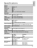
Page 21: ...t Power Consumption 9 W 13 W 29MP HD PRO C and 29MP HD PRO M only Power Connector 2 pin terminal block Environmental Operating Temperature 10 C to 50 C 14 F to 122 F Storage Temperature 10 C to 70 C 14 F to 158 F Humidity 20 80 Relative humidity non condensing Certifications UL 60950 CSA60950 EN 60950 1 CE ROHS WEEE Electromagnetic Emissions FCC Part 15 Subpart B Class A IC ICES 003 Class A EN 550...

Page 22: ...ts distributors dealers agents or employees shall create another warranty or modify this warranty This warranty states Avigilon s entire liability and your exclusive remedy against Avigilon for any failure of this product to operate properly In no event shall Avigilon be liable for any indirect incidental special consequential exemplary or punitive damages whatsoever including but not limited to d...

Page 23: ... 9 27 11 Avigilon Corporation ...

Reviews: