EX5000 Release 8.2.2 Installation Manual P/N 600-00073-001 Rev 02
- 97 -
Appendix I: Wiring Diagram – Power, Dimming Bus, and
Exceedance Horn
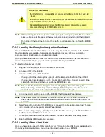
Note:
Port assignments shown are nominal assignments. You can select ports as required in
Maintenance Mode setup pages, as long as sensors are wired to the corresponding pins.


