


EX5000 Release 8.2.2 Installation Manual P/N 600-00073-001 Rev 02
- 35 -
Note:
Use the matrix as a general guideline only. GPS manufacturers are constantly improving and
upgrading their products. Always refer to the
Installation Manuals
that come with the
GPS/FMS to confirm configuration and setup parameters. Additionally, keep in mind that not
all GPS configurations can be used with all aircraft.
There are two interface configurations that the MFD uses to connect with the GPS:
•
GAMA 429
•
RS-232
EX5000 MFDs support both GAMA 429 and RS-232. However, GAMA 429 Graphics is the only
configuration from the GPS capable of providing heading information if the GPS is being used as the
heading source (see Section 5.13 Map Setup for a complete explanation on setting up the various
heading configurations within the MFD).
5.5.1 GAMA 429 Graphics Setup
If your GPS is capable of GAMA 429 Graphics output, use the wiring diagram in Appendix J:
Wiring
Diagram – GPS/FMS
when installing the MFD.
Note:
Using a 429 graphics output allows for the display of curved flight segments and approach
data, if that data is available.
To setup a GAMA 429-capable GPS:
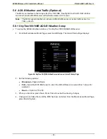
1.
From the Maintenance Mode Page, press
GPS Setup
. The GPS Setup Page displays:
Figure 8: GPS Setup, GAMA 429
2.
Configure the following:
•
Receiver
—Select GAMA 429 Graphics Format.
•
Port—
Select ARINC1.
Note:
Selecting Port=None indicates that a GPS is not connected to the MFD. In this case, the MFD
software does not expect GPS input.


