

WWW.AVENTURACCTV.COM
DOCUMENT V1.2
Quick Start Guide
Related Series Models:
CAM-AHY-2B-212V-IR, CAM-AHY-5B-212V-IR
The product comes with the following components:
1. Camera Device.
2. Attachment screws and anchor pack.
3. L-Key for adjustment of camera bracket.
4. Software CD
Be sure no parts are missing from the product before
installation.
Information in this document is subject to change without notice. As our
products are subject to continuous improvement, Aventura
Technologies reserves the right to modify product design, specifications
without notice and without incurring any obligation. E&OE
©2016 Aventura Technologies, Inc. All rights reserved.
AVENTURA TECHNOLOGIES, INC.
HEADQUARTERS
48 Mall Drive, Commack, New York 11725 U.S.A.
Tel: +1.631.300.4000 Fax: +1.631.434.7000
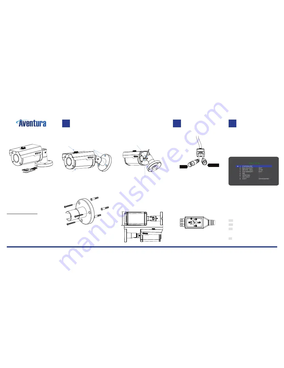
INSTALLATION
1. Below is an overview of the parts of the
camera, showing how the completed
product would look.
Visor adjustment
Attachment Location
Focus-zoom adjustment*
*Some models like shown have auto-focus zoom and offer
no adjustment access. Access panel would be located at
the bottom of the camera to provide access to the manual
focus-zoom levers.
Use the bracket base for locating drill positions
and attach the camera using the supplied anchors/wall
plugs and attachment screws.
Note: You need be sure of the waterproof surround of the camera
& cables if externally fitted, consult professional if in doubt some
buildings it is possible that thermal dampness or moisture can get
into stud walls. Always be safe with cables and connections.
2. All adjust to position and angle of the bullet
using the adjustment hex bolts located on the
rear base of the camera. Use the L-Key turn
anti-clockwise to loosen. The adjustment has
teeth inside to lock into a position to prevent
drifting.
Angle Adjustment Nut
Twist position adjustment
5. Focus and zoom for camera image and field of
view require the external adjustments, with the
device being powered on is the only way to be
sure to obtain the correct position and desired
angle. Autofocus zoom models do not require
any adjustment as this is achieved
automatically.
NOTE: You may opt to not tighten completely until focus and
zoom adjustments have been completed. Once properly
focused and zoomed, tightening these nuts prevent the
camera view from drifting.
6. CAD Dimensions Inch (mm)
CONNECTION & OSD
The camera has the following termination cables.
1.
BNC Interface
: Connect to appropriately qualified
cable and attach to the DVR / XVR recording unit.
NOTE: RG59 Cable should be of high quality and using pure
copper inner core, low-cost cables using copper over steel may
give unexpected results for video signal and should not be used.
2 Power Interface
: Standard CCTV 12V power
connection, connect to a qualified regulated
supply.
DC12V (600mA):
12V DC power input terminal. Make sure
to follow correct polarity with the + as the inner pin of the
supply
Some models may include an OSD built into the cable,
whilst the device supports OTC (Over the Cable) control,
the on cable is here for when DVRs may not support the
OSD function from the recording device.
Control of OSD is simple with the little four direction
control, and push down to activate. We referred the push
as entering or
OK
in the rest of this guide.
OSD MENU USAGE
The camera comes with a typical set of parameters for
image output used by the camera. Using the OSD, you are
able to affect the camera performance to suit the
installation requirement of the device.
Note: You can also use the OSD from your DVR/XVR device if
the control over cable method is supported, check the manual for
this device.
Press
○
E
to enter the OSD menu you are presented with
the following top-level Menu.
You navigate around using the
○
L Left,
○
R Right,
○
U
Up,
○
D Down
positions using the control button
.
To
change or activate a setting press down
○
E
entering
. This
will activate or allow change the current position value.
The currently selected position is indicated by the two circle
as highlighted in red.
Where there is a
←ˡ
on the right side of selection, this
indicates an option or will change to another menu level.
Note: From top-level menus you can Exit, to retain changes for
when the camera is restarted, you must activate the Save option.
BACK Goes back to previous menu options
NEXT Goes forward to next menu options
SAVE All modified settings you have changed will be
written to the camera memory, so when it’s reset or
restarted the changes made are kept.
EXIT Closes the OSD menu from the system, retaining
current changes, but only until the next power cycle of the
camera.
6 Inch ( 152 mm )
2In
ch
( 53m
m
)
U
D
L
R
E
1
2
○
1
○
2
○
3
3
BNC RG59
12V DC 5.5x2.1mm


