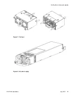


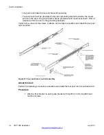


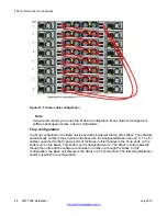

Figure 9: Optional four-post rack mount brackets
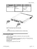
3. Slide the switch into the rack.
4. Fasten the switch to the equipment rack with rack mount screws.
5. Verify that the switch is securely fastened to the rack.
You can proceed with the installation by connecting power and network connections
to the switch.
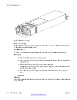
Installing optional four post rack mount brackets
Before you begin
VSP 7000 four post server rack mount kit — AL7011001–E6
Tool requirements
• a Phillips screwdriver to attach brackets to the switch and the switch to the rack.
• a Hex wrench to assemble and attach the optional four-post rack mount brackets.
Rack requirements
• Space of 2.8 inches (7.1 cm) for each switch in an E1A or 1EC standard 19 inch (48.2
cm) equipment rack and T1A 23 inch (58.5 cm) equipment rack.
• Appropriate rack space to accommodate 1U switch height (44 mm).
Installing optional four post rack mount brackets
VSP 7000 installation
July 2013 33
Summary of Contents for VSP 7000 Series
Page 4: ...4 VSP 7000 installation July 2013 Comments infodev avaya com ...
Page 6: ...Installing an MDA 66 Appendix A Hardware reliability 67 6 VSP 7000 installation July 2013 ...
Page 28: ...Installation preparation 28 VSP 7000 installation July 2013 Comments infodev avaya com ...
Page 68: ...Hardware reliability 68 VSP 7000 installation July 2013 Comments infodev avaya com ...


