


Maintenance-Object Repair Procedures
555-233-143
8-960
Issue 1 May 2002
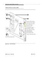
TN2312AP IP Server Interface (IPSI)
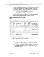
Figure 8-51.
TN2312AP IPSI
Spit
fire2
TDM Bus
Packet Bus
T
N
23
12
AP
Clock Status LED (Amber)
Push Button Switch
Circuit Pack Alarm LED (Red)
In Use LED (Amber)
Test In Progress LED (Green)
A
0
1
Switch ID (One character)
Cabinet Number (Two digits)
Ethernet Link Status
Services Interface (RJ45)
Control Network Interface (RJ45)
IP
Serv
e
r
In
tfc
(Top bar for Services Interface,
LA
NIS
NC
Es
DSP
MPC
8260
Eth
erne
t
Eth
erne
t
RS2
32 +
Control Network Interface (RJ45)
Maintenance
Board
Maintenance Board Interface
Interface
Clocks
Bottom bar for Control Network)
Summary of Contents for S8700 Series
Page 50: ...Maintenance Architecture 555 233 143 1 26 Issue 1 May 2002 ...
Page 74: ...Initialization and Recovery 555 233 143 3 12 Issue 1 May 2002 ...
Page 186: ...Alarms Errors and Troubleshooting 555 233 143 4 112 Issue 1 May 2002 ...
Page 232: ...Additional Maintenance Procedures 555 233 143 5 46 Issue 1 May 2002 ...
Page 635: ...status psa Issue 1 May 2002 7 379 555 233 143 status psa See status tti on page 7 406 ...
Page 722: ...Maintenance Commands 555 233 143 7 466 Issue 1 May 2002 ...


