


Isolating and Repairing Packet-Bus Faults
Issue 1 May 2002
4-83
555-233-143
Tools for Packet-Bus Fault Isolation, Correction
The following tools may be required on-site to perform packet-bus fault isolation
and correction.
■
TN771D Maintenance/Test circuit pack for use in stand-alone mode, and
the connectors and cables necessary to install it (see
(Maintenance/Test Circuit Pack)’’ on page 8-1157
).
■
A replacement for the TN771D Maintenance/Test circuit pack in the system
may be needed. See
‘‘Entering and Exiting Stand-Alone Mode’’ on page
.
■
A backplane pin-replacement kit may be required (see
Packet-Bus Faults’’ on page 4-103
). If the kit is not available, replacement
of a carrier may be required.
What is the Packet Bus?
The packet bus is a set of 24 leads in the backplane of each EPN. Twenty of
these leads are data leads, three are control leads, and one lead is a spare. This
distinction is important only for understanding why some circuit packs can detect
only certain faults; the distinction does not affect fault isolation and repair. Each
EPN has its own packet bus, and there is one Packet Bus MO (PKT-BUS) for
each EPN. Unlike the TDM bus, the packet bus is not duplicated. However, it has
several spare leads and, in a critical-reliability system (duplicated PNC), these
spare leads are used to recover from some packet-bus faults.
The packet bus carries various types of information:
■
Signaling and data traffic destined for other port networks and/or Center
Stage Switches (CSSs). The TN570 EI circuit pack provides packet-bus
access for these connections.
■
ISDN-BRI signaling information for ISDN-BRI stations, data modules and
ASAI adjunct connections. The TN556 ISDN-BRI circuit pack provides
packet-bus access for these connections.
■
ISDN-PRI signaling information carried in the D channels of ISDN-PRI
facilities connected to the switch. The TN464F Universal DS1 circuit pack
provides packet-bus access for these connections.
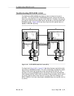
A server’s interface to an EPN’s packet bus is by way of an Ethernet link to the
EPN’s TN2312 IPSI circuit pack, through the IPSI’s Packet Interface circuit, and
to the packet bus. When servers are duplicated, there are two IPSIs in each EPN.
The TN771D Maintenance/Test circuit pack provides packet-bus maintenance
testing and reconfiguration capabilities. The circuit packs mentioned here are
discussed in more detail in
Summary of Contents for S8700 Series
Page 50: ...Maintenance Architecture 555 233 143 1 26 Issue 1 May 2002 ...
Page 74: ...Initialization and Recovery 555 233 143 3 12 Issue 1 May 2002 ...
Page 186: ...Alarms Errors and Troubleshooting 555 233 143 4 112 Issue 1 May 2002 ...
Page 232: ...Additional Maintenance Procedures 555 233 143 5 46 Issue 1 May 2002 ...
Page 635: ...status psa Issue 1 May 2002 7 379 555 233 143 status psa See status tti on page 7 406 ...
Page 722: ...Maintenance Commands 555 233 143 7 466 Issue 1 May 2002 ...


