


Maintenance-Object Repair Procedures
555-233-143
8-772
Issue 1 May 2002
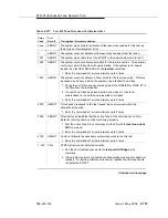
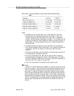
b. This corresponds to error code 1281 from the Hardware Error Log and
indicates a failure of Test #237. This condition is usually due to the failure
of this EI circuit pack or a failed EIEI or SNI circuit pack counterpart.
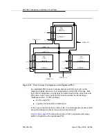
c. This is the normal state for an active PN EI circuit pack that is also the bus
master (Expansion Archangel) in the EPN.
d. This is the normal state for an active EI circuit pack that is not the bus
master (Expansion Archangel) for an PN. This applies only in the
direct-connect configuration where the EI circuit pack in an PN is
connected via a fiber link to an EI circuit pack in the other PN.
e. This is the normal state for a standby EI circuit pack in a PN.
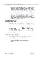
NOTE:
In a PN, its TN775C Maintenance (MAINT) circuit pack monitors the sanity
of the EI circuit pack. If the EI circuit pack should cycle between sane and
insane several times, the Maintenance circuit pack will hold the EI circuit
pack reset. If a new EI circuit pack is installed in the PN, and the red LED
remains lit, the PN’s Maintenance circuit pack should be removed because it
may be holding the new EI circuit pack reset. This condition could present
itself if there is a link problem to the PN, and the PN experiences several PN
restarts. The Maintenance circuit pack may be reinstalled after the EI circuit
pack has been physically inserted and the EI circuit pack’s red LED has
gone off.
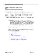
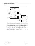
The link between two active EI circuit packs or between an active EI circuit pack
and an active SNI circuit pack is involved in synchronization. The EI circuit pack
reports slip errors if synchronization is not operating properly. When diagnosing
synchronization problems, the EI circuit packs should be examined as a possible
cause.
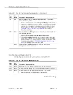
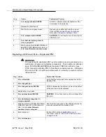
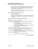
Expansion Interface LEDs
The EI circuit pack has the standard red, green, and amber LEDs. The red and
green LEDs have the traditional uses: red means some alarm condition and
green indicates maintenance testing in progress. The amber LED is used to
provide useful visual status information. The state of the amber LED is very
important when executing the Expansion Interface Manual Loop-Back Procedure.
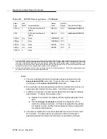
The possible amber LED states are shown in
.
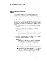
Upon power-up, the red and green LEDs turn on and off. The amber LED goes to
its appropriate state.
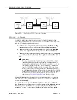
To determine which PNC (and which EIs in an PN) is active and which is standby,
use the status port-network and status PNC commands. Alternately, visual
inspection will show that the active EI circuit packs will have their amber LED on
solid (for an inter-PN EI in a direct connect system) or blink a pattern of 2 seconds
on and 200 ms off. The standby PNC EI circuit packs will have their amber LEDs
off. See
for the possible EI amber LED states.
Summary of Contents for S8700 Series
Page 50: ...Maintenance Architecture 555 233 143 1 26 Issue 1 May 2002 ...
Page 74: ...Initialization and Recovery 555 233 143 3 12 Issue 1 May 2002 ...
Page 186: ...Alarms Errors and Troubleshooting 555 233 143 4 112 Issue 1 May 2002 ...
Page 232: ...Additional Maintenance Procedures 555 233 143 5 46 Issue 1 May 2002 ...
Page 635: ...status psa Issue 1 May 2002 7 379 555 233 143 status psa See status tti on page 7 406 ...
Page 722: ...Maintenance Commands 555 233 143 7 466 Issue 1 May 2002 ...


