


ATM Tips
Issue 1 May 2002
4-35
555-233-143
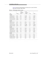
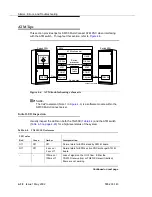
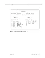
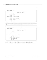
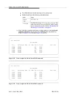
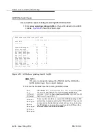
Figure 4-11.
Screen output for display circuit-packs 1
display circuit-packs 1
CIRCUIT PACKS
Cabinet: 1 Carrier: A
Cabinet Layout: five-carrier Carrier Type: processor
*** PROCESSOR BOARDS NOT ADMINISTERABLE IN THIS SCREEN ***
CIRCUIT PACKS
Cabinet: 1 Carrier: B
Cabinet Layout: five-carrier Carrier Type: port
Slot Code Sfx Name Slot Code Sfx Name
00: 11: TN464 C DS1 INTERFACE
01: 12: TN464 F DS1 INTERFACE
02: TN2305 ATM PNC EI 13: TN767 F DS1 INTERFACE
03: 14: TN767 C DS1 INTERFACE
04: TN754 C DIGITAL LINE 15: TN760 D TIE TRUNK
05: TN746 B ANALOG LINE 16: TN760 D TIE TRUNK
06: TN753 DID TRUNK 17:
07: TN771 D MAINTENANCE/TEST 18:
08: TN747 B CO TRUNK 19:
09: TN556 B BRI LINE 20:
10: TN767 C DS1 INTERFACE
’#’ indicates circuit pack conflict.
Summary of Contents for S8700 Series
Page 50: ...Maintenance Architecture 555 233 143 1 26 Issue 1 May 2002 ...
Page 74: ...Initialization and Recovery 555 233 143 3 12 Issue 1 May 2002 ...
Page 186: ...Alarms Errors and Troubleshooting 555 233 143 4 112 Issue 1 May 2002 ...
Page 232: ...Additional Maintenance Procedures 555 233 143 5 46 Issue 1 May 2002 ...
Page 635: ...status psa Issue 1 May 2002 7 379 555 233 143 status psa See status tti on page 7 406 ...
Page 722: ...Maintenance Commands 555 233 143 7 466 Issue 1 May 2002 ...


