Avaya P130 User’s Guide
17
Chapter 4
Installation and Setup
The Avaya P130 is ready to work after you carry out the installation instructions
given below. All the P130 ports provide complete connectivity and no configuration
is required to make the system work.
Setting up the Module
The P130 front panel contains LEDs, controls, 10/100BaseTX ports and a console
connector. The status LEDs and control buttons provide at-a-glance module status
information.
The P130 allows you to make the following network connections from the ports on
the front panel:
•
The P133G2 and P134G2 modules have two SFP (3.3 V-powered) ports for plug-
in 1000BASE-SX or LX SFP GBIC Transceivers. Alternatively, you can cascade
up to four P130 modules via a 2-m long Avaya X130CK cable. This proprietary
low-cost cable has built-in connectors which fit directly into the SFP slot. The
cable provides up to 2Gbps traffic throughput between modules.
•
P133F2 has two fixed 100BASE-FX SC ports.
•
P133GT2 has two fixed 100/1000BASE-T RJ-45 ports.
•
P133T has no uplink ports.
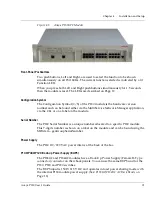
Figure 4.1
Avaya P133T Module
Summary of Contents for P130 SMON
Page 1: ...Avaya User s Guide AVAYA P130 WORKGROUP SWITCH SOFTWARE VERSION 2 9 July 2002 ...
Page 2: ......
Page 12: ...List of Figures x P130 User s Guide ...
Page 14: ...List of Tables xii P130 User s Guide ...
Page 24: ...Chapter 1 Overview 10 Avaya P130 User s Guide ...
Page 28: ...Chapter 2 P130 Front and Back Panels 14 Avaya P130 User s Guide ...
Page 30: ...Chapter 3 Applications 16 Avaya P130 User s Guide ...
Page 50: ...Chapter 5 Avaya P130 CLI Architecture Access Conventions 36 Avaya P130 User s Guide ...
Page 94: ...Chapter 6 Avaya P130 CLI 80 Avaya P130 User s Guide ...
Page 146: ...132 Avaya P130 User s Guide ...
Page 156: ...Appendix C Index of all CLI Commands 142 Avaya P130 User s Guide ...


